(IMC Konfigurationsmanual version 1, engelska)
Introduction
IMC: The master control station for managed properties, places all energy devices and data on a common platform for management and monitoring.
Managed properties today consist largely of prefabricated systems with embedded control, monitoring, and communications capabilities. KTC IMC is a unique, powerful tool that gets property systems to work together, placing all managed systems on a single platform, making all their data easily accessible. This means that you can control devices/systems from a wide range of manufacturers rather than be restricted to any one brand.
KTC Integration Master IMC integrates all of these systems to get them to cooperate and give you full control of the entire property. KTC integrates all devices and retrieves data from all technical systems on the property.
KTC IMC is scalable to any degree. It is typically installed in a cabinet in the central heating room of a large building with many apartments or offices to integrate the heating/cooling/ventilation systems in that building. It can also remotely control the systems in any number of other buildings from the same location.
Physically the IMC is a small embedded computer with network connections. All communications to programmer, user, PLC:s and other devices are via IP. The IMC doesn’t not include a screen so an external tablet, PC OS is needed for programmer and user.
Manual Conventions
The user manual is built more as a “how to” than as a reference. We go through the different steps in configuring and programming a plant using IMC. When there is user input required the dialog box and screen dumps is included, and a table describing the different fields and their meaning.
Since a lot of fields is generic, when possible there is a section in beginning of each chapter describing general info on the fields that is valid for all parts of the chapter.
There are a lot of fields that is rarely used so since this is not a reference manual they are sometimes excluded. The field description has a layout as below. The R column stands for “Required” and indicates that the field must always have data. The “Ex.data” column is only present in cases where the author finds it necessary to give some hint on good naming conventions, or reasonable values.
| Field | R | Description | Ex. Data |
|---|---|---|---|
System overview
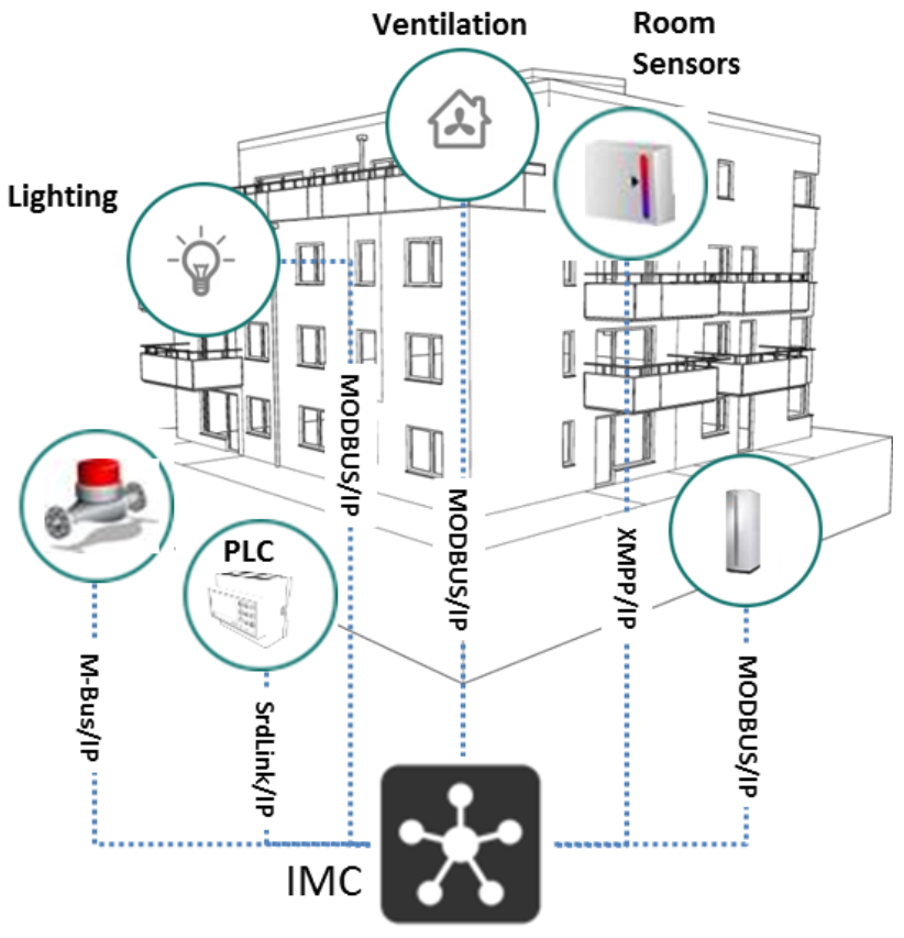
The picture below describes how a system using IMC typically is built.
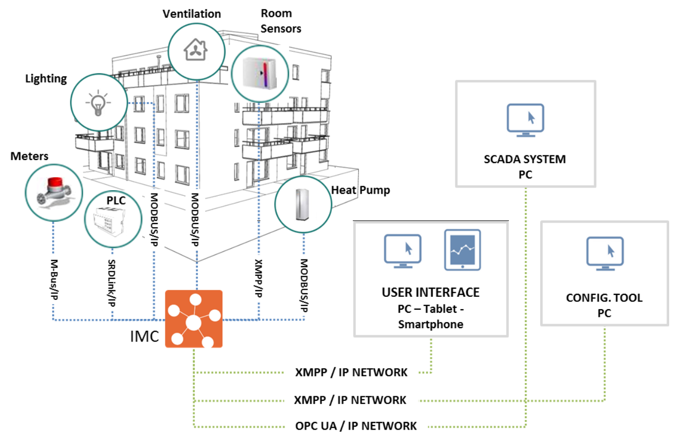
In Version 1.0 you can connect M-Bus, ModBus, SRDLink and XMPP devices over IP. More protocols are continuously added. The IMC creates functionality and control between different automation devices. As an extra it also creates a one GUI for the user so that he can control all different system for example from a tablet.
Getting started
To configure an IMC you basically need to get it connected to a network, having the software tool “Clayster Management Client” CMT installed on your PC that is connected to the same network.
The end-user rarely need the CMT, he will instead use the built in web-server in IMC to access the system. This can be done from a pc, a tablet or a smartphone.
Much of the configuration that you do using the CMT can also be done directly in the web GUI, however not as efficient when doing larger amount of configuring.
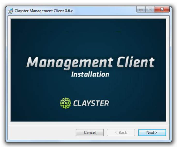
Installing the CMT Client
The CMT Client is the “configuring tool” for IMC and is included when an installer is educated on IMC System at KTC. The installer will receive the software at the education, or upgrades later from ktc.se The setup file is named Clayster.Management.WPF.Setup.exe.
Run the setup file on the computer that will be used for configuring IMC. CMT Client is a windows tool and needs Windows operating system on a pc.
Follow the instructions given from setup program.
Start IMC for the first time
There are two ways to connect to an IMC for the first time. The following describes these two different ways.
By using DHCP
default on IMC network port 1
Connect the network cable to IMC IP port 1 to an existing network that has a DHCP-server.
The IMC is default set to DHCP on IP port 1 and will be assigned an IP address.
If your network has a connection between DHCP-Server and DNS Server you will be able to reach the IMC by hostname. Hostname is default IMC-xxxxxx where xxxxxx is the last 6 numbers/letters in the mac-address of the IMC. You can find this as a label on the box that IMC is delivered in.
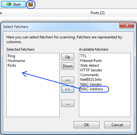
Test if it works by doing (on command line in windows) ping IMC-0b10fc (use the mac on your IMC) If the above doesn’t work, download the program “Angry IP Scanner”. With help of this program you can do a search on all devices at your local IP range that respond to "ping" on port 50100 (default port for communication with IMC). For more information and downloads of Angry IP Scanner see http://angryip.org
By comparing the result of a "scan" before and after IMC connected to the network, you can find your IMC. Normally only IMC will responds on port 50100, and then only the IMC’s connected to the network.
Tip: Enable MAC Address in Angry IP. Then you will also see the MAC address of the devices that responds on port 50100. Compare the MAC address in the list with the one on the sticker on the IMC.
By using static IP-address
default on IMC network port 2
Connect the network cable to IMC IP port 2. This network card is default set to static IP address 192.168.0.5.
By configuring the network card on your PC to be in the same range (e.g. 192.168.0.10), you can connect directly to your IMC.
Connect the CMT Client to IMC
When starting the CMT Client the dialog below will be displayed. It allows you to connect to the IMC and start configuration. Once you have connected it will be easier to reconnect since the connections are saved under “recent connections”
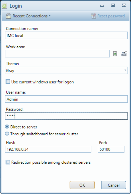
| Field | R | Description | Default on IMC |
|---|---|---|---|
| Connection Name | R | Simpler name than IP to remember | |
| User | R | User name | Admin |
| Password | R | Password | Admin |
| Host | R | Hostname or IP-Address of IMC | |
| Port | R | Port number to communicate on | 50100 |
| Direct to Server | R | Always use this for IMC | |
| Work Area | If you have saved a file with configuration of your workspace you can load this here. |
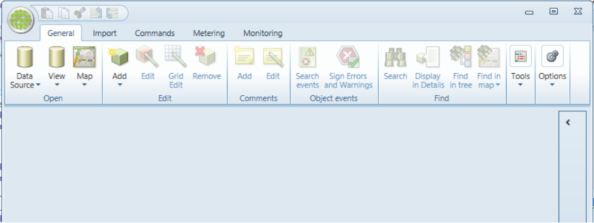
Once connected the screen will look as below. Then everything is ready to start configure…
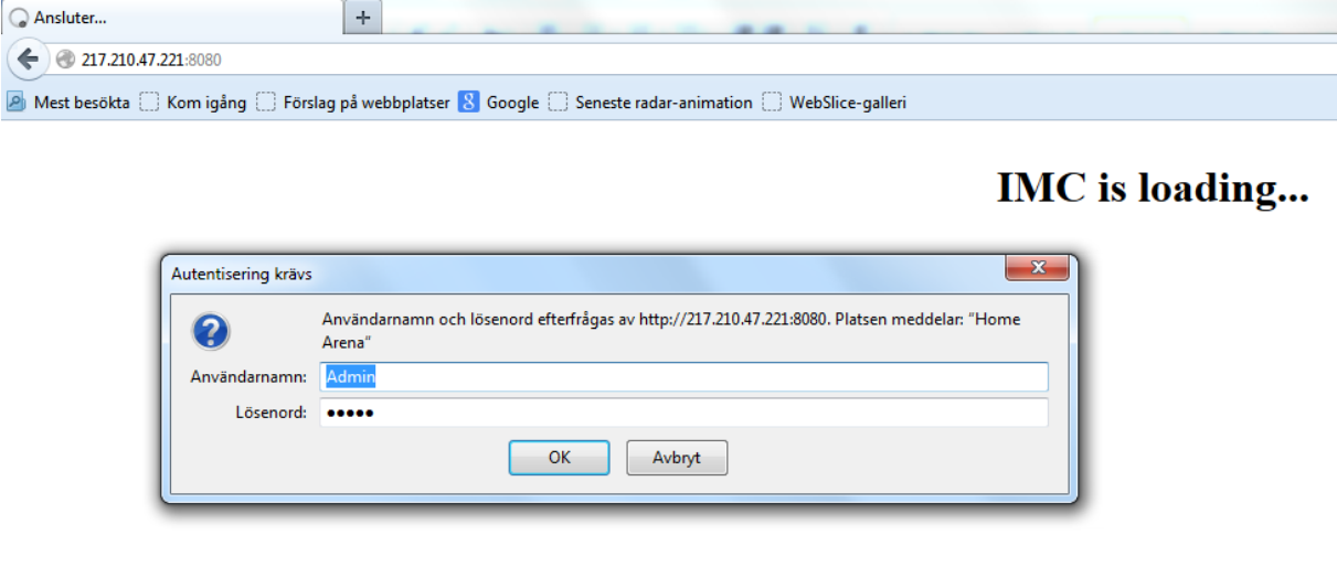
Access IMC through web interface.
Connect by opening a browser and enter the IP address or the name of your IMC followed by the port number: 8080. Fill in the username and password and click "OK".
Connecting devices
This section for the installation engineer and describes how to configure and connect to different devices using different protocols.
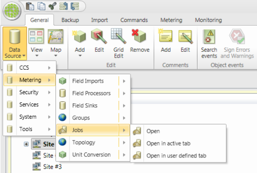
All device configurations are done in the topology. The topology is the network of devices that IMC controls. To access the topology, select datasource – metering – topology as shown in picture below.
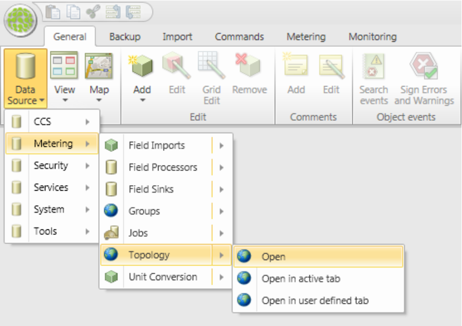
Once topology is opened it will get a tab and you access it by clicking on that tab.
This chapter is divided into some general information and then one section for each protocol available at writing time. The number of protocols is continually extended, and will be described in future versions of this manual.
General information on topology
On an IMC the standard topology has the following “top” nodes:
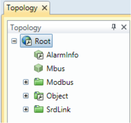
- Alarminfo - Special node that provides functionality for Sumalarms for all other nodes.
- Mbus - All Mbus devices connected to the system will be added to this node.
- Modbus - ModBus devices.
- SRDLink – KTC SRDLink Devices.
- Object – Integration function and calculations.
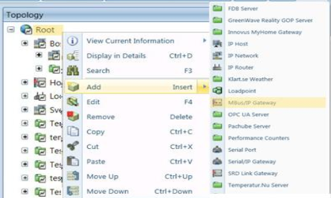
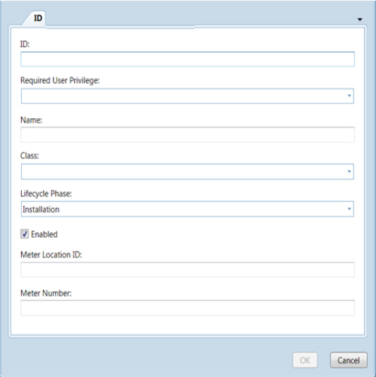
When adding new nodes just select the node that you want to add a device or node under, right click and select “add”. Depending on where and what you want to add a dialog box will appear. However many of the fields is similar between different objects that you add. A Dialog box similar to the one below will appear.
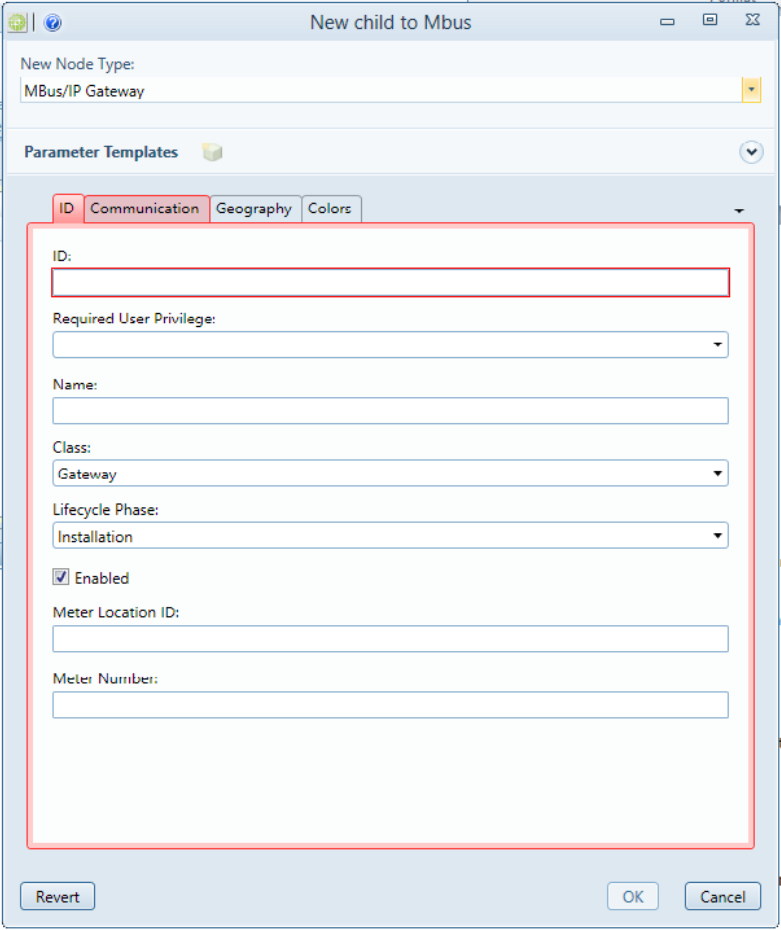
Some fields and tabs in the dialog box are unique to the type of object you want to add, but many fields are identical. This manual will describe the generic fields valid for all objects. More specific fields for a specific type of object are described in the part of the manual that describes these objects.
| Tab | Field | R | Description | Ex. Data |
|---|---|---|---|---|
| Id | Id | R | Unique id for the node. In many cases the system will suggest an id based on the parents id. It is important to have some kind of system for naming nodes/devices. | B01.TA01.AI01 B01.FF01.A60 |
| Required User Privilege | .. | .. | .. | .. |
Handling ModBus devices
Modbus is a standard serial communications/ control protocol for use with programmable logic controllers (PLCs). It provides communication between devices connected on buses or networks. Modbus allows for communication between many networked devices. An example is a system that measures temperature and humidity and communicates the results to a computer. Modbus is often used to connect a supervisory computer with a remote terminal unit (RTU) in supervisory control and data acquisition (SCADA) systems.
The protocol defines function codes and the encoding scheme for transferring data as either single points (1-bit, coils) or as 16-bit data registers. This basic data packet is then encapsulated according to the protocol specifications for Modbus ASCII, RTU, or TCP.
Modbus protocol is defined as a master/slave protocol. That means a device operating as a master will poll devices operating as slaves. The master will write and read data from slave devices.
Types of Modbus registers and their usage
- Coils are 1-bit registers, are used to control discrete outputs, and may be read or written.
- Discrete Inputs are 1-bit registers used as inputs, and may only be read.
- Input registers are 16-bit registers used for input, and may only be read.
- Holding registers are the most universal 16-bit register, may be read or written, and may be used for a variety of things including inputs, outputs, configuration data, or any requirement for "holding" data.
ModBus nodes
The below is a typical structure for ModBus Nodes
- Modbus Root node
- ModbusGateway
- ModbusNode
- Coil Register
- DiscreteInput Register
- Modbus Group
- Modbus group
- Register group
- Holding Register
- Input Register
- Modbus Register Group
- Coil Register (a digital read/write object): Compares read/write with relay.
- DiscreteInput Register (a digital read object): Digital input
- Holding Register (an analog read/write object): To persist whatever is written.
- Input Register (read object): Reads analogue values.
- ModbusNode
- ModbusGateway
Adding new Modbus devices to your topology tree
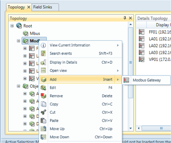
Begin with a ModBus gateway.
Right-click the Modbus root node, and select the "Add/Modbus Gateway" option:
On the ID tab
-
ID required
A unique ID for the system to use for this node. Can be autocreated via the Autocreate function.
-
Description optional
A freely chosen description of the node. It will appear in the tree.
-
Required User Privilege optional
If empty, all can view this node. If not empty, this node (and all its children) can only be viewed by users having this Privilege ID.
-
Name required
A secondary name (string) for the node. It appears in the tree. Is used in the Autocreate ID function.
-
Class required
Select the type of device. Possible values are:
- ColdWater
- Gas
- Electric
- Concentrator
- etc.
-
Phase required
- Test: cannot erase nodes.
- Production: cannot erase nodes or edit some com parameters.
- Installation: all new nodes default
-
Enabled optional
Enables function. Default= true
-
MeterLocationId optional
ID of the meter location. Is often used in meter data application to assign values. It is recommended to assign a meterLocationId. It is used by engineers to locate meters/sensors upon customer request.
-
MeterNumber optional
Often used in metering apps to assign values.
Suggested naming conventions
- In general, try to create groups that match the functions in a Modbus unit, typically one group for each sensor, or for each control function.
- If the unit is to be connected to KTC Scada, try to match SRDLink objects to avoid creating new interfaces at the top level.
-
If IMC is serving only one building, use the name of the unit connected.
Example: a single building Alarm setting could be named LS01
-
If serving several buildings, add some information to identify the building connected.
Example: If there is a gateway for each building, it could be named ModbusGW-Bldg
Naming convention for IDs
It is suggested to use AAxx where AA is the recommended abbreviation and xx is the ModBus address. There might be (for example): a Modbus gateway with an IP-address, and a main module with a ModBus address, and a number of submodules. This naming convention makes it easy to organise them.
Note: The ID can be auto-created as a concatenation of node names in the path to the final object. Take this into consideration when assigning Modbus Names. See Autocreate below.
On the Communications tab
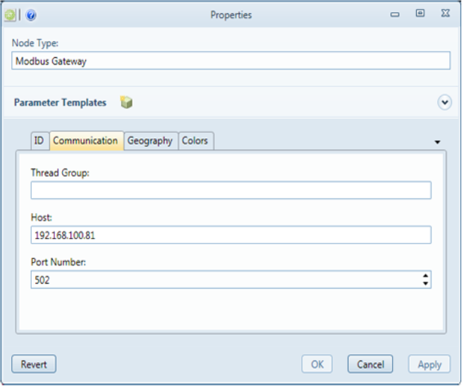
-
ThreadGroup optional
Thread Groups can help performance. Nodes of the same thread group are read using the same thread. If not specified, the node automatically assigns a thread group with the same name as the node ID.
-
Host required
Host Name or IP Address of the machine or device.
-
Port required
Port Number to use when connecting to the machine or device. standard for ModBus is 502.
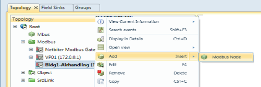
Then add a ModBus Node to the gateway
Note that you can add a ModBus node manually as follows or via the scan function (see ModBus scan ). Often only one on a Gateway, but can be several.
Right-click the Modbus gateway selecting the Add/Modbus Node option:
On the ID tab
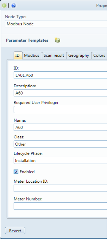
-
ID required
A unique ID for the system to use for this node. Can be autocreated via the Autocreate function.
-
Description optional
A freely chosen description of the node. It will appear in the tree.
-
Required User Privilege optional
If empty, all can view this node. If not empty, this node (and all its children) can only be viewed by users having this Privilege ID.
-
Name required
A secondary name (string) for the node. It appears in the tree. Is used in the Autocreate ID function.
-
Class required
Select the type of device. Possible values are:
- ColdWater
- Gas
- Electric
- Concentrator
- etc.
-
Phase required
- Test: cannot erase nodes.
- Production: cannot erase nodes or edit some com parameters.
- Installation: all new nodes default
-
Enabled optional
Enables function. Default= true
-
MeterLocationId optional
ID of the meter location. Is often used in meter data application to assign values. It is recommended to assign a meterLocationId. It is used by engineers to locate meters/sensors upon customer request.
-
MeterNumber optional
Often used in metering apps to assign values.
On the Modbus tab
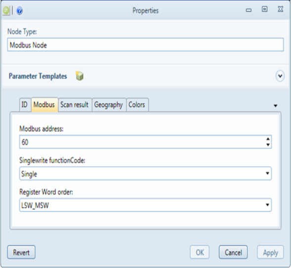
-
Modbus address required
Enter the Modbus address from the project documentation.
-
Singlewrite functionCode required
Function code to use when writing to a single holding register.
Options are:
- Single
- Multiple
-
Register Word order required
Register word order to use when registering 32 bit values.
Options are:
- LSW-MSW
- MSW-LSW
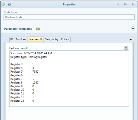
On the Scan Result tab
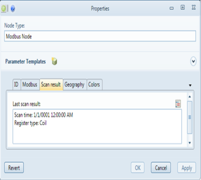
-
Scan Result
Shows the results of the last scan. Scan is done by right-clicking on that Modbus node you want to search and select " scan detailed".
Set " Register type ", "Starting address", "Ending Address" and "Maximum quantity per message”. Click "OK" to execute.
On the Geography tab
Not necessary
On the Colors tab
Not necessary
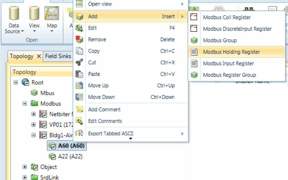
Add a Modbus Register
You can add a register group to create a group that connects variables in Modbus related to a specific object.
In this example, add a single Register.
Right-click the Modbus node, selecting the Add option and then the register of choice, in this case, a Modbus Holding Register:
On the ID tab
-
ID required
A unique ID for the system to use for this node. Can be autocreated via the Autocreate function.
-
Description optional
A freely chosen description of the node. It will appear in the tree.
-
Required User Privilege optional
If empty, all can view this node. If not empty, this node (and all its children) can only be viewed by users having this Privilege ID.
-
Name required
A secondary name (string) for the node. It appears in the tree. Is used in the Autocreate ID function.
-
Class required
Select the type of device. Possible values are:
- ColdWater
- Gas
- Electric
- Concentrator
- etc.
-
Phase required
- Test: cannot erase nodes.
- Production: cannot erase nodes or edit some com parameters.
- Installation: all new nodes default
-
Enabled optional
Enables function. Default= true
-
MeterLocationId optional
ID of the meter location. Is often used in meter data application to assign values. It is recommended to assign a meterLocationId. It is used by engineers to locate meters/sensors upon customer request.
-
MeterNumber optional
Often used in metering apps to assign values.
On the Register tab
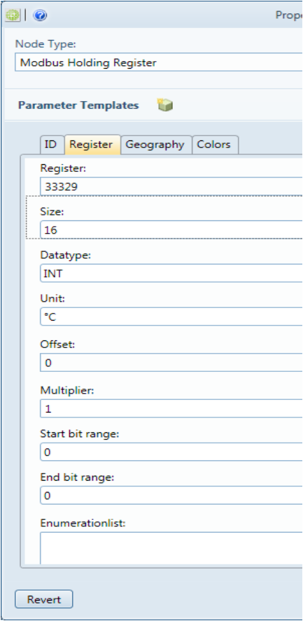
Note: At this level of the tree, different nodes can have different attributes. The tabs presented in this section show all possibilities. Some of the following attributes/tabs might NOT be available to you, depending on the node type you are adding:
-
Register required
Enter register address. Default addresses are usually specified in unit documentation.
-
Size required
Select value size, 16 or 32 bit
-
Datatype required
Select register datatype (signed, unsigned or float)
-
Unit required
Select units (°C, kWH, sec, etc)
-
Offset optional
Enter offset that will be added/subtracted from collected value. Typically for calibration, normally not used.
-
Multiplier optional
Example: If a value is expressed in 0.1 degrees, enter a multiplier to process it to a more useable number.
-
Start bit range optional
Select bit range start (1-32) 0=disable (reads entire reg)
-
End bit range optional
Select bit range end (1-32) 0=disable (reads entire reg)
-
Enumeration list optional
Add string in format (Index=String) to create an Enumeration list. Note the icon that exports this to the editor if you prefer to work there.
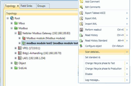
ModBus scan
You can use the built-in scan function to read the Modbus registers in the Modbus device. Right-click the Modbus Node, selecting the Scan detailed option:
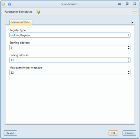
-
Register type
Select the type of register to search for.
-
Starting address
Starting address for individual address search range.
-
Ending address
Ending address for individual address search range.
-
Max quantity per message
The maximum number of Registers to include per message.
Recommended naming conventions
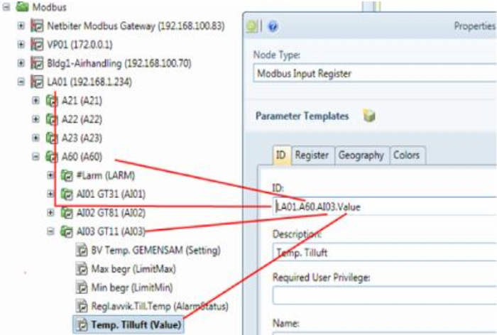
The format for naming is NodeName.NodeName.RegisterName. It is further recommended to use the same object names as in SRDLink objects. This avoids creating new top level groups and improves performance, particularly if used in connection to KTC-SCADA. The following image shows the names typically used. Consult the KTC-modules guide for the latest updates.
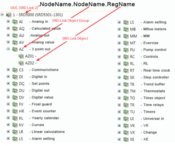
The following image shows how the various identification components are displayed in the tree, and a logical approach to configuring these entries.
Note: the Autocreate option for auto-generating the IDs to be used in the system:
Summary of recommended naming tips
-
Use the same abbreviations used in the SRDLink module when naming nodes. SRDLink is the software protocol for KTC-specific products. Performance is thus improved, particularly when connecting to other KTC modules such as KTC SCADA.
-
If you have variables that don’t easily convert to the SRDLink model, you can add each to a random group with any name that makes sense to you.
-
Note that the Description fields for each node, add visible information to the tree that makes it easy to locate an object for management/trouble-shooting etc. Examples:
-
Include Register addresses in the descriptions of folders that organise ModBus registers. A60 might indicate a folder of airhandling variables at address 60 behind the Modbus gateway.
-
In addition to SRDLink abbreviations, text that indicates usage such as building/apartment numbers, or titles such as Settings, Airhandler etc. are useful in descriptions.
-
-
To translate a Boolean/int variable to text, use the Enumeration list function.
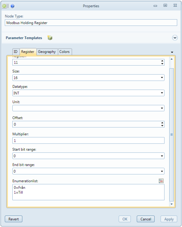
The value will be shown as text described in the Enumerationlist:

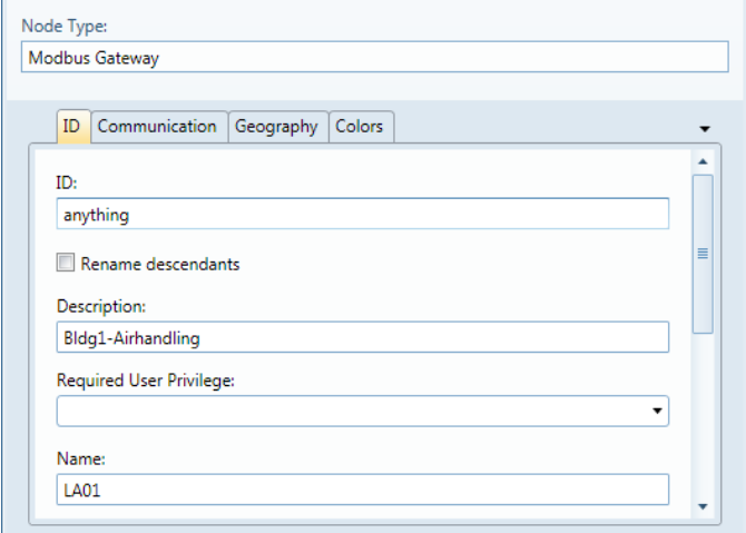
Autocreate
For Modbus objects, you can use Autogenerate to create the final ID of the object that is used by the system. This function automatically concatenates the contents of the Name fields for all nodes in the path to the final object. The following section demonstrates this.
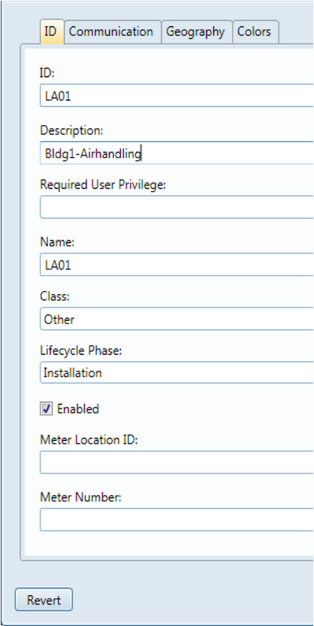
When configuring the Modbus ID tabs (for gateways or sub-nodes), you must enter something in the ID field in order to make the OK button available. If you plan to use Autogenerate, you can enter anything you want because it will be replaced when the final ID is calculated. In this example, the gateway ID is anything, the name is LA01 (the SRDLink abbreviation for an air handling unit with the gateway contained). The description is Bldg1-Airhandling. It will appear in the tree to inform the user of the unit’s purpose. The address of the unit will also appear in the tree from what you enter on the Communication tab:
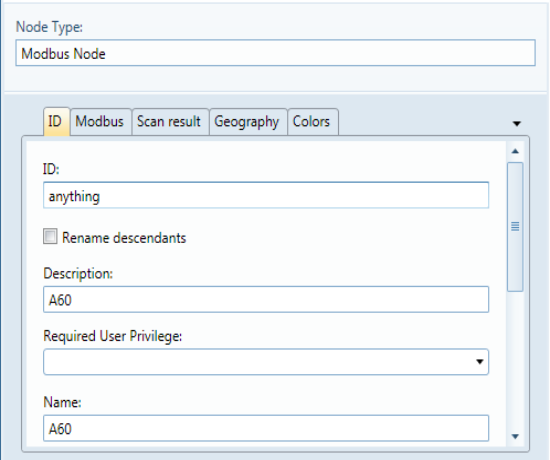
Adding a subnode
You can again enter anything in the ID field and then enter a name in the Name field. This example adds a node named A60. The description is also A60. This will appear in the tree as A60 (A60) with the description first and name in parenthesis. In this case, A60 is used to inform the user of the unit address behind the integrated gateway (default addresses are usually specified in unit documentation):
Configure as many levels of sub-nodes as you wish. When you are finished, right-click the Modbus GW or Modbus Node you have added them to, selecting the Set standard ID option:
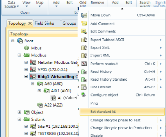
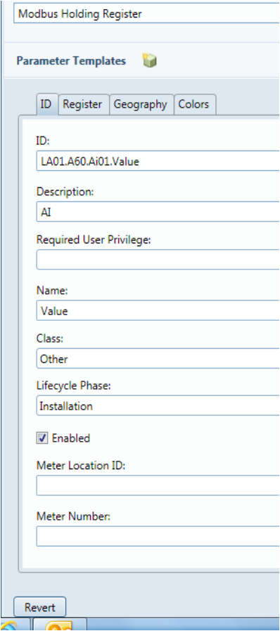
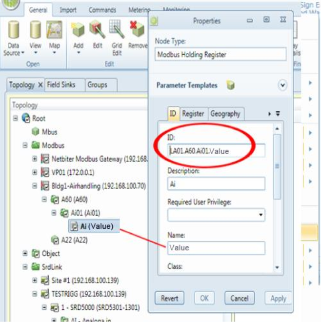
Now looking at the Properties tab of a final object (below, it’s Ai (Value): you can see that:
-
The node Names are unchanged in the tree
-
The Ids have now been replaced with the concatenation of node names in the path leading to the final object: In this example, it is LA01.A60.Ai01.Value identifies the holding register that contains the Ai value.
SRDLink
SRDLink is the software protocol for KTC-specific products. KTC products also supports other protocols but the native protocol is SRDLink.
-
SrdLinkGateway
-
SrdLinkNode
-
SrdLinkObject
-
SrdLinkObjectGroup
- SrdLinkObject
-
-
To add a SRDLink device to your topology tree
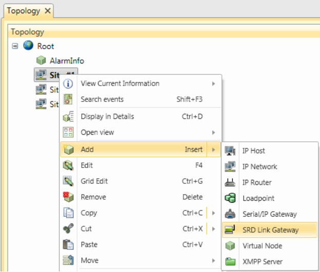
Begin by adding a SRDLink gateway node:
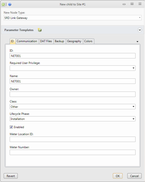
On the ID tab
Enter the ID and Name (often the same).
-
Id required
A unique Id for the system to use for this node.
-
Required User Privilege optional
If empty, all can view this node. If not empty, this node and children can only be viewed by users with this Privilege ID.
-
Name optional
A secondary name (string) for the node. It appears in the tree. Is used to inform about usage of the objects.
-
Class required
Select the type of device. Possible values are:
- ColdWater
- Gas
- Electric
- Concentrator
- etc.
-
Phase required
- Test: cannot erase nodes.
- Production: cannot erase nodes or edit some com parameters.
- Installation: all new nodes default
-
Enabled optional
Enables function. Default= true
-
MeterLocationId optional
ID of the meter location. Often used in meter apps to assign values. It is recommended to be used by engineers to locate meters/sensors.
-
MeterNumber optional
Meter apps can use to assign values.
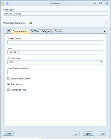
On the Communication tab
Enter the IP-address and port number to reach the unit, standard port for SRD Link is 10001.
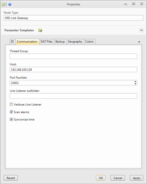
-
ThreadGroup optional
Thread Groups can help performance. Nodes of the same thread group are read using the same thread. If not specified, the node automatically assigns a thread group with the same name as the node ID.
-
Host required
Host Name or IP Address of the device.
-
Port required
Port Number to use when connecting to the device. Standard for SRDLink is 10001.
-
Line listener subfolder optional
Enter the name of a line listener subfolder. Leave empty if no line listener is desired.
-
Verbose line listener optional
If checked, additional info is provided in the line listener.
-
Scan alarms optional
Scans the alarm queue.
-
Synchronize time optional
Synchronize times.
DAT Files tab
This is an alternative for adding SRDLink nodes. See: Create SRDLink nodes via DAT file (Offline configuration)
Backup
Here we can see when the last backup of the PLC is made. To make a PLC backup, right click on the SRD-Link Gateway and select "Read DAT file". The files will by default be stored under: C:\ProgramData\IMC\DATFiles
Geography tab
unnecessary.
Colors tab
unnecessary.
Three ways to add SRD-Link devices
-
Scan
automatic scanning of devices. This is the easiest way and requires a minimum of time. This method requires that devices are accessible from the IMC server.
-
Import DAT-files
We use this method when we want to prepare the OPC server and not yet have communication to the devices.
-
Manually build the SRD-Link topology
This method is the most time consuming and is primarily used to add single objects in a device.
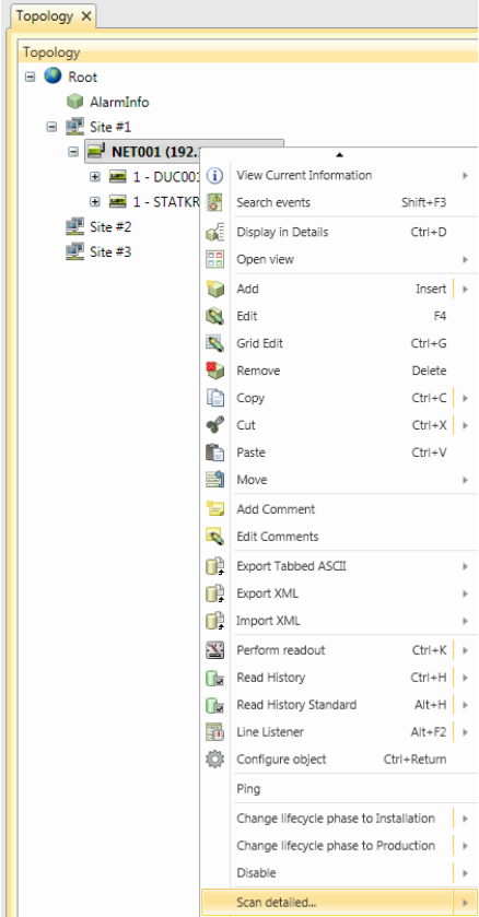
Create SRDLink nodes via scan option
Right click on the SRD-Link Gateway and select “scan detailed”
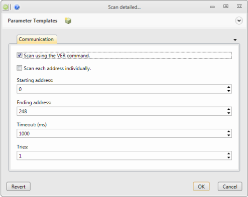
-
Use VER
Default method. Fastest scan but can be unreliable with many devices connected to the bus.
-
Individual search
More time consuming but more reliable with a large number of devices connected.
-
Starting address
Beginning address for the individual address scan range.
-
End address
End address for individual address scan range.
-
Timeout
Timeout in ms for address queries.
-
Tries
Number of tries before returning a failure.
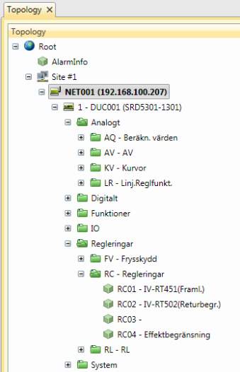
Every existing device and object connected to the SRD-Link Gateway will automatically be placed in your topology tree.
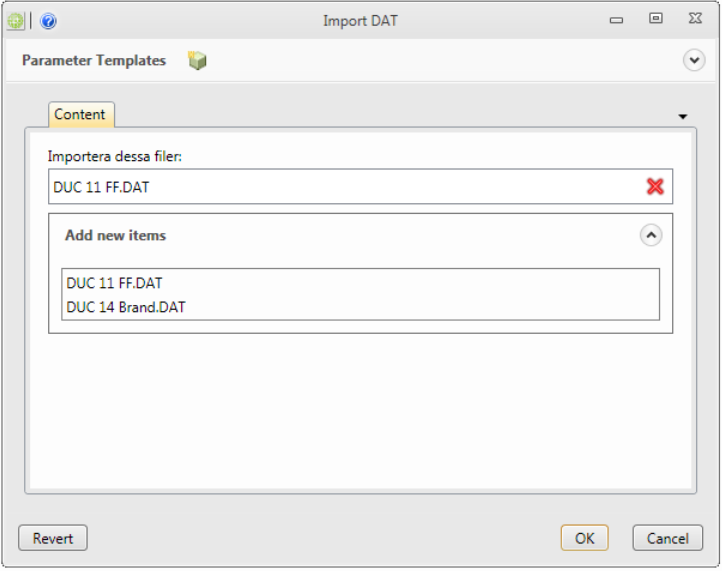
Create SRDLink nodes via DAT file (Offline configuration)
For convenient logistics, you can pre-program a building with an offline configuration. This method allows you to create a SRDLink gateway node with SRDLink devices and objects by importing a DAT file at the gateway level.
DAT Files are created by using the KTC Tool Automate, for more details read the manual for Automate.
Start by uploading your already configured DAT files to the "SRD Link Gateway".
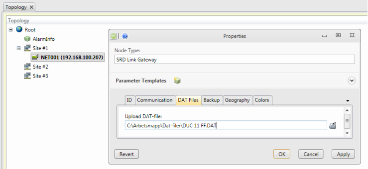
Right click on the “SRD Link Gateway” and choose “Import DAT”.
Create SRDLink nodes/Objects manually
Add a SRD-Link device node to the gateway by right-clicking the SRD Gateway and selecting the Add/DUC option:
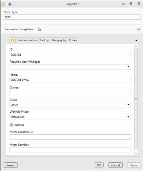
-
Id required
A unique Id for the system to use for this node.
-
Required User Privilege optional
If empty, all can view this node. If not empty, this node (and all its children) can only be viewed by users having this Privilege ID.
-
Name optional
A secondary name(string) for the node. It appears in the tree. Is used to inform about usage of the objects.
-
Class required
Select the type of device. Possible values are:
- ColdWater
- Gas
- Electric
- Concentrator
- etc.
-
Phase required
- Test: cannot erase nodes.
- Production: cannot erase nodes or edit some com parameters.
- Install: all new nodes default)
-
Enabled optional
Enables function. Default= true
-
MeterLocationId optional
ID of the meter location. Is often used in meter data application to assign values. It is recommended to assign a meterLocationId. It is used by engineers to locate meters/sensors upon customer request.
-
MeterNumber optional
Often used in meter data application to assign values.
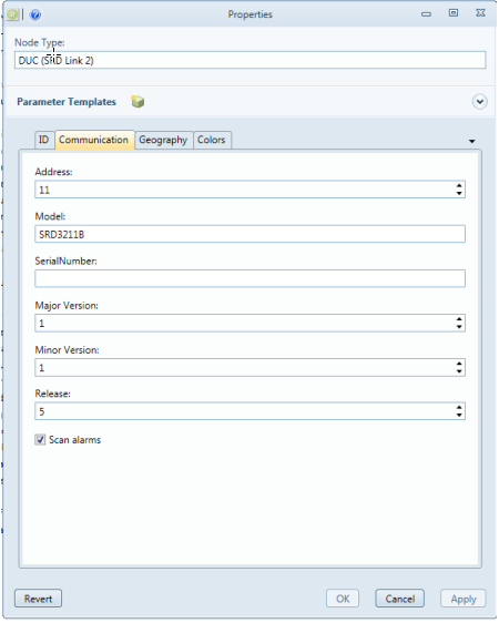
On the Communication tab
Enter the SRD-address and model type of the unit.
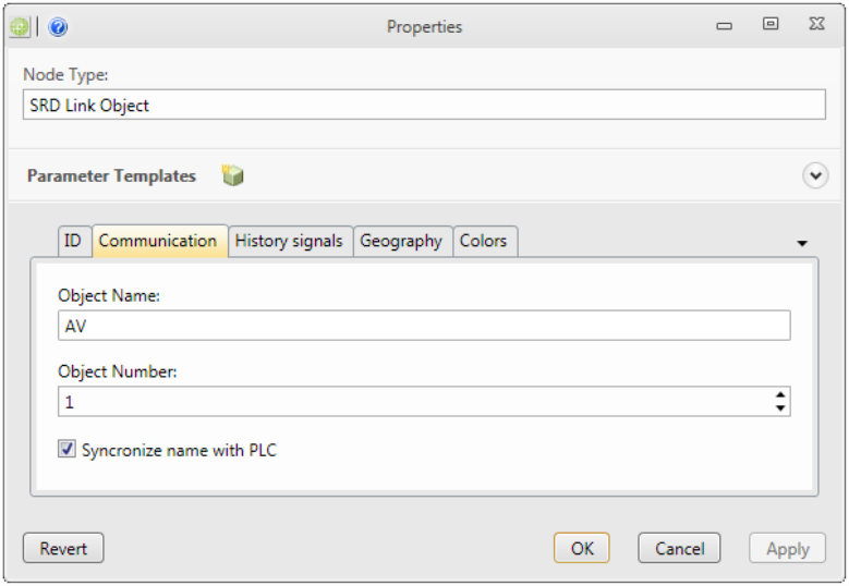
After this you can add a SRD-Link Object/ SRD-Link Object Group(used to organize the objects) Just right click and chose the type of object you want to add.
On the Communication tab you have to fill in the Object Name and number.
Connecting KTC device COM1025 using “SCADA-StatusClient” function with IMC.
In the communication product KTC COM1025 there is a function called "SCADA Client Status". This feature enabled communication between COM1025 and former Adepto OPC server without the use of fixed IP addresses. At IMC, we have implemented functionality to be able to support KTC COM1025 fully in the IMC.
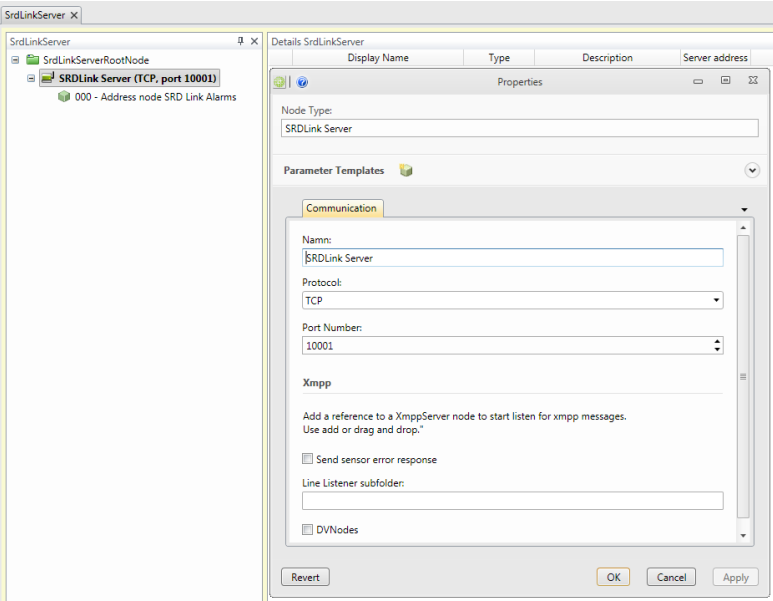
The first thing we must do is to add a SRDLink server. This is to allow communication between COM1025 and the IMC server.
Open Data source/IMC/SRDLinkServer.
Add SRDLink Server
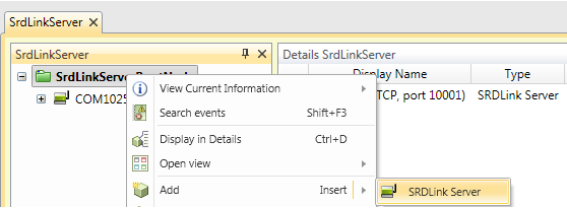
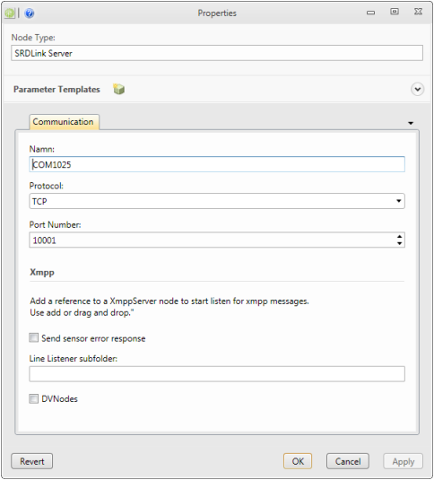
-
Name
Enter a name for the node
-
Protocol
TCP/UDP (in this case we use TCP)
-
Port Number
Enter a valid port number for the connection to the host machine. Default for this application is 10001.
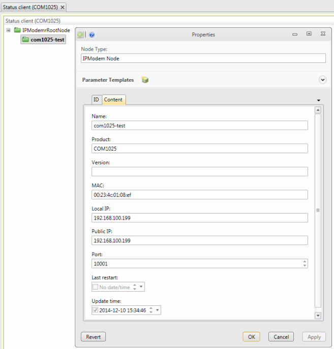
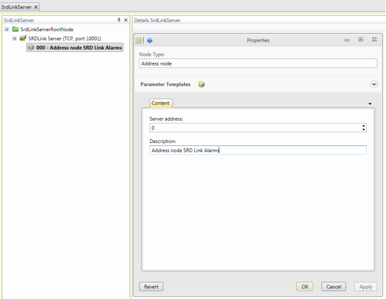
Those COM1025 devices configured to talk to your IMC server will now appear in the tab Data source / IMC / Status Client (COM1025).
What remains now is to create a reference to Topology tree. We do this by adding a SRDLink Gateway reference.
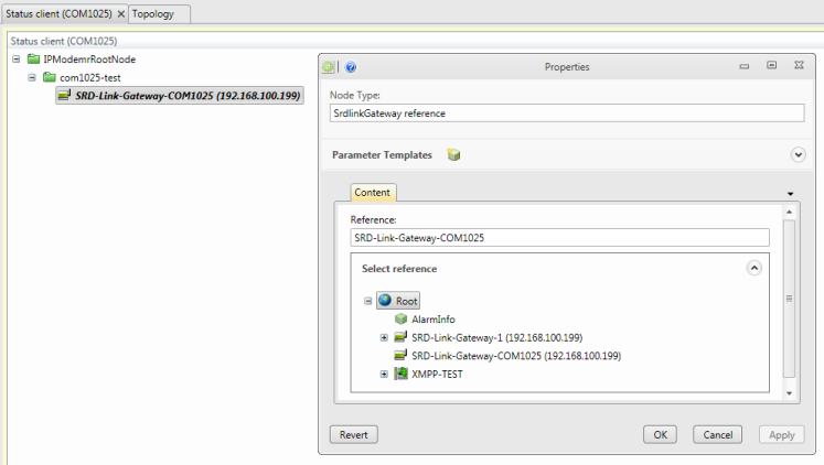
Note: This reference replaces any communication settings previously made in Topology / SRDLink Gateway with new ones from the Status client.
Connecting KTC device using XMPP
In IMC, you also have the ability to connect your devices through XMPP. Connection via XMPP does not require fixed IP addresses and only port for outgoing traffic must be opened (default XMPP port 5222). An XMPP server must be available for this type of communications solution.
Add a new XMPP Server
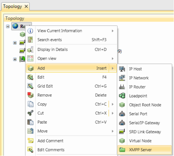
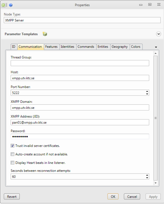
In the Communications tab
-
Thread Group optional
All nodes belonging to the same thread group, will be read using the same thread.
-
Host required
Enter an IP address or DNS name for the host machine
-
Port Number required
Enter a valid port number for the connection to the host machine.
-
XMPP Domain required
Name of the domain hosted by the XMPP server.
-
XMPP Address (JID) required
XMPP address of the client that will perform communication with XMPP devices.
-
Password required
Password corresponding to the XMPP address.
-
Trust invalid server certificates optional
If checked, invalid server certificates will be accepted during connection.
-
Auto-create account if not available optional
If checked, a new account will be created on the XMPP server. After created, the flag will be cleared.
-
Display Heart beats in line listener optional
If checked, the line listener will display when heart beat messages is sent to the XMPP server.
-
Seconds between reconnection attempts
If connection to XMPP server is missing, reconnection attempts will be performed with this interval.
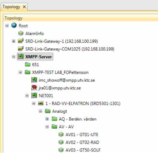
Any valid connections will show up in the XMPP topology:
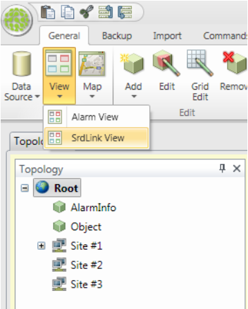
Custom View IMC
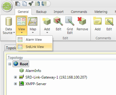
The IMC includes two different custom views. These two are the Alarm view and SRDLink view. The Alarm view is used to monitor and acknowledge alarms. SRDLink view can be used to monitor realtime values of Object, see when the last backup was taken and activate trend collection on Objects and more.
Both are closely linked to the Topology tree and displays information depending on which node in the tree you have selected.
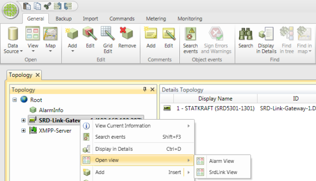
Custom views are accessed via the View / Alarms view alt. SRDLink view. A prerequisite for being able to open custom views is that Topology is already selected.
Alternatively, custom views can be opened via the Topology tree / Open View.
Alarm view
Alarm view is a list with the possibility to Filter, acknowledge and delete alarms. Alarms are displayed related to the selected node in the topology tree. It means that you will see all alarms in the IMC if you select the top node.
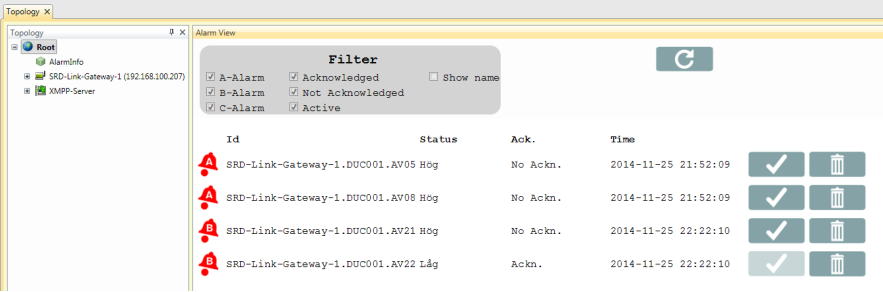
| Acknowledging alarms is done by clicking: |  |
| Permanently remove an alarm is done by clicking: |  |
| Refresh the Alarm view by clicking: |  |
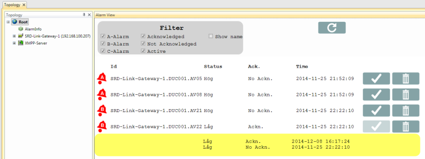
By clicking on an alarm, you will get more information about the specific alarm.
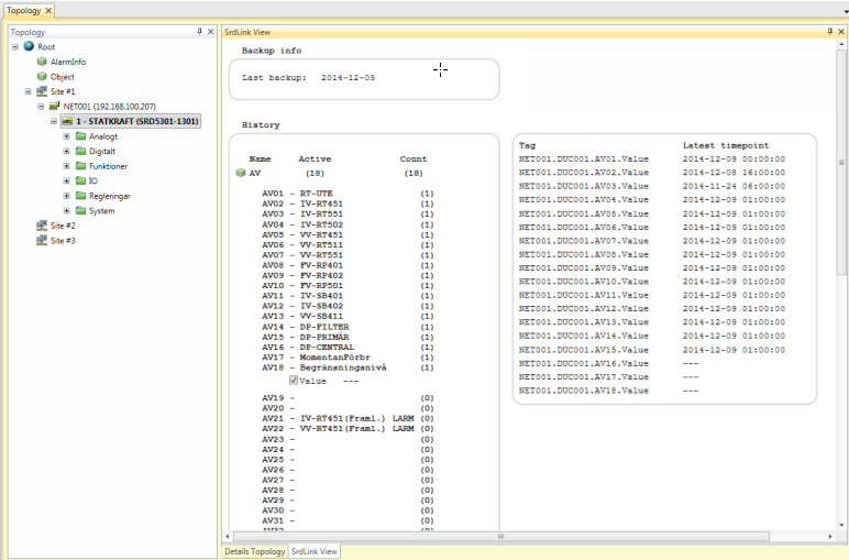
SRDLink view
At the gateway level, it provides information about Backups, current alarm settings in the PLC (click on the PLC name) as well as connection info.
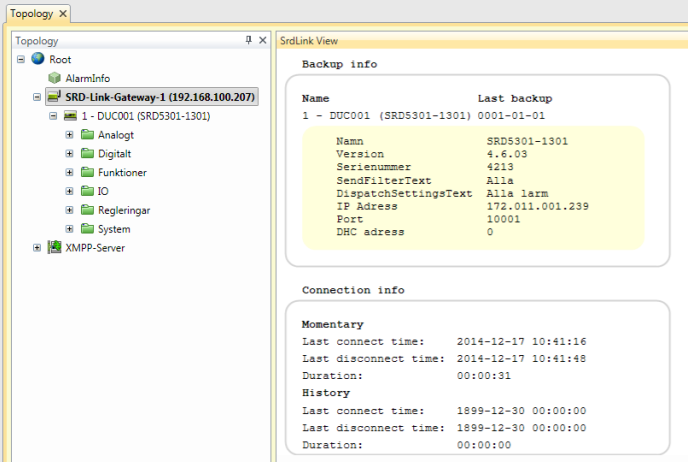
At the PLC level, you can see when the last backup was taken. You are also able to activate historical collection of objects
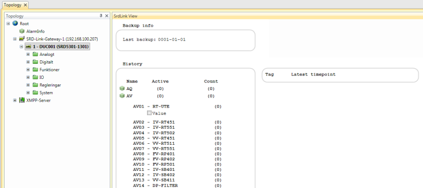
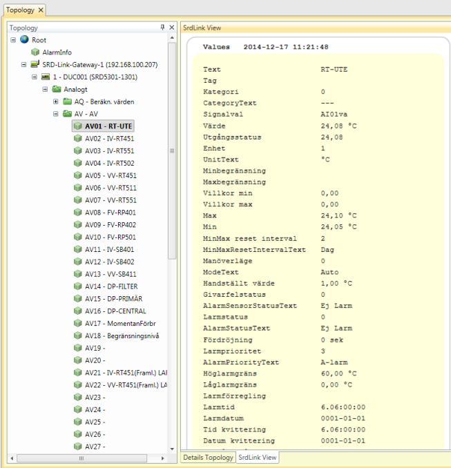
On the object level, you will find real-time data for the selected object.
Mbus
M-Bus (Meter-Bus) is a European communications standard for the remote reading of gas or electricity meters. M-Bus is also usable for other types of consumption meters. The M-Bus interface is made for communication on two wires, making it very cost effective.
M-Bus was developed, for example, to measure the consumption of gas or water in the home. This bus fulfils the special requirements of remotely powered or battery-driven systems, including consumer utility meters. When queried, the meters deliver the data they have collected to a common master, such as a computer, connected at periodic intervals to read all utility meters of a building.
Other applications for M-Bus are alarm systems, flexible illumination installations, heating control, various sensors etc.
Note that M-Bus provides functions for scanning the network, automatically registering discovered nodes that are connected to the system.
Examples of Mbus devices:
- MBusIPGateway
- MbusNode
- SVM TBox Mbus Temperature Sensor
- Westermo AD01
- Mbus Adapter
- MBussMaster
- R232 Master
- Sharky 773
- Sharky 775
- Enermet11EVLMBus
- PiiGAB900
- MBusInterface
Add an Mbus device to your topology tree:
- Right-click in the topology tree where you want to add the new node (here, it is the Root node).
- Select the Add option for the correct node-type. In this case, add an Mbus gateway to accept the specific Mbus devices you want to connect:
On the ID tab
-
Id required
A unique Id for the system to use for this node.
-
Required User Privilege optional
If empty, all can view this node. If not empty, this node (and all its children) can only be viewed by users having this Privilege ID.
-
Name optional
A secondary name (string) for the node. Gives info to users about the node, instead of the id attribute.
-
Class required
Select the type of device. Possible values:
- ColdWater
- Gas
- Electric
- etc.
-
Phase required
- Test: cannot erase nodes.
- Production: cannot erase nodes or edit some com parameters.
- Install: all new nodes default)
-
Enabled optional
Enables function. Default= true
-
MeterLocationId optional
ID of the meter location. Is often used in meter data application to assign values. It is recommended to assign a meterLocationId. It is used by engineers to locate meters/sensors upon customer request.
-
MeterNumber optional
Often used in meter data application to assign values.
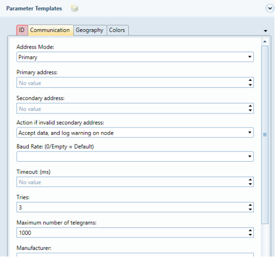
On the Communication tab
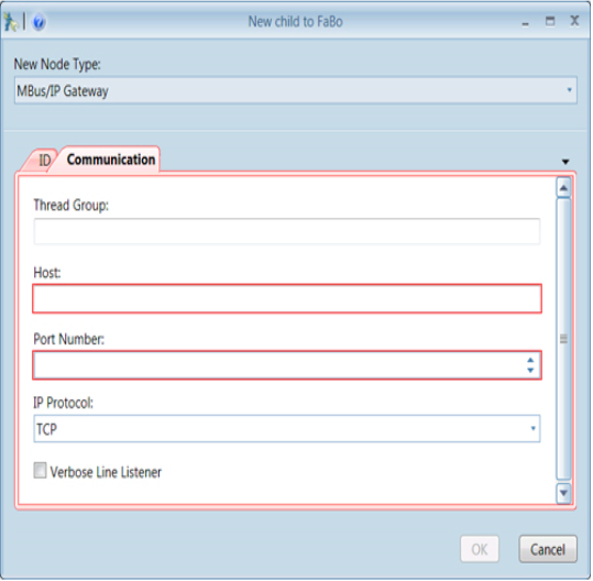
-
Thread Group optional
Thread Groups can help performance. Nodes of the same thread group are read using the same thread. If not specified, the node automatically assigns a thread group with the same name as the node ID.
-
Host required
Host Name (string ) or IP Address of the machine or device.
-
Port Number required
Port Number to use when connecting to the machine or device. KTC Devices normally connects on port 10003, UDP
-
IP protocol optional
Specifies the IP protocol to use. Possible values are: TCP (Default), UDP
-
Verbose Line Listener optional
If true, interpretation information will be made available in the line listener. Default is false.
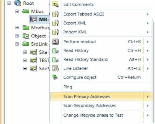
Scan meters/devices.
You can scan for either primary or secondary address. Recommended is secondary.
When you have established an M-Bus gateway, you can use the scan function to discover all devices connected on the bus. Right-click the gateway, selecting one of the Scan options.
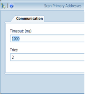
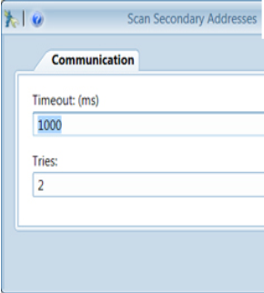
-
Timeout optional
Value in milliseconds. Default is 0
-
Tries optional Max inclusive value is 100. Default is 3.
Any nodes discovered are automatically correctly placed in the topology tree.
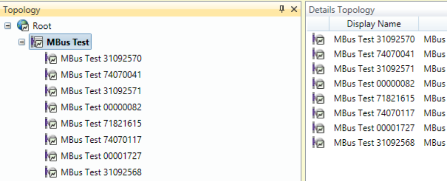
The example shows 8 meters discovered by scan function.
Offline devices
To configure devices that is not online, do “Add Mbus Node (General)”.
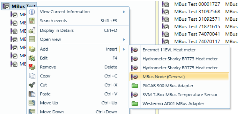
You need either the primary or the secondary adress of the MBus-meter to be able to add it manually to the topology. It is also necessary to select adress mode to primary/secondary depending on the adress you enter.
Copy, backup and restore
You can copy all or part of the tree in the topology and then copy it to another part of the tree or to another project. Right click and select copy (CTRL + C) then paste(CTRL + V).
You can also do a full backup of your IMC project. This is done by first selecting "Backup" tab at the top.
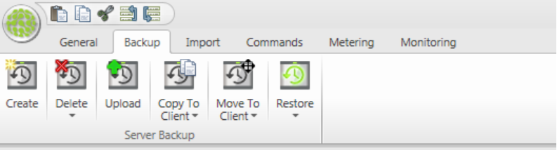
-
Create
Create a new server backup (With option to copy or move the backup to a client when finished)
-
Delete Backup
Delete a server backup
-
Upload
Upload a locally saved backup to the server
-
Copy to Client
Copy a locally saved backup to the client
-
Move to Client
Copy a backup file from the server and save on the client and then delete the backup file on the server
-
Restore
Restore a server backup
Creating integrated functionality
IMC places all of your building’s systems on a common platform. This enables you to converge the functionality from several different systems to vastly increase their scope and utility.
Generic info on creating calculation objects
Much of the integration logic is created in the “Objects” part of topology tree. The different objects that can be added (version 1.0 ) are:
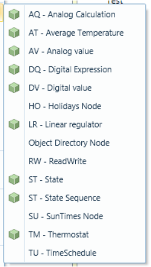
AQ – Analog Calculation Object
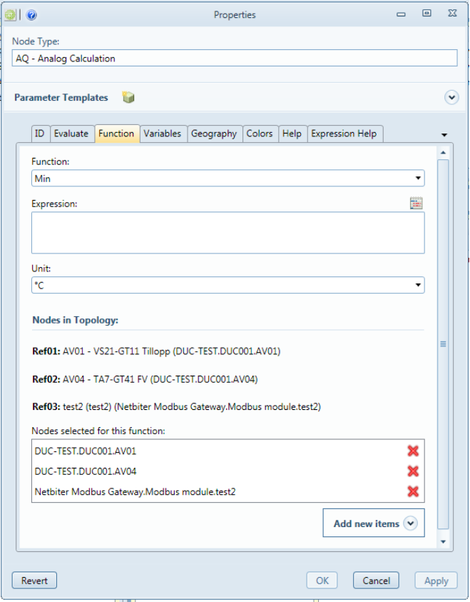
The analog calculation object is used to perform a calculation between a number of analog inparameters
It is possible to perform more advanced calculations using a script language.
For more “ease of use” there is also a number of standard calculations included, similar to those in KTC PLC: s. (Min,Max,Average) etc.
In this example, we first create a “object directory node” by right-clicking in topology tree. The node is called “_Examples”. The result should similar to below, although only with “Examples” and not all the AQ in the picture.
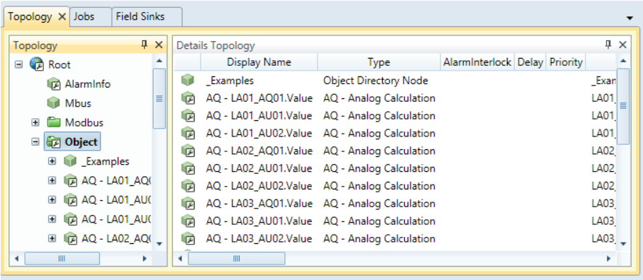
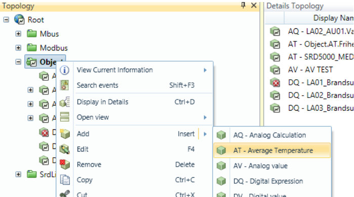
Next step is to right-click _Examples, select add, select “AQ – Analog Calculation Object”. You will get a dialog box locking like the one below.
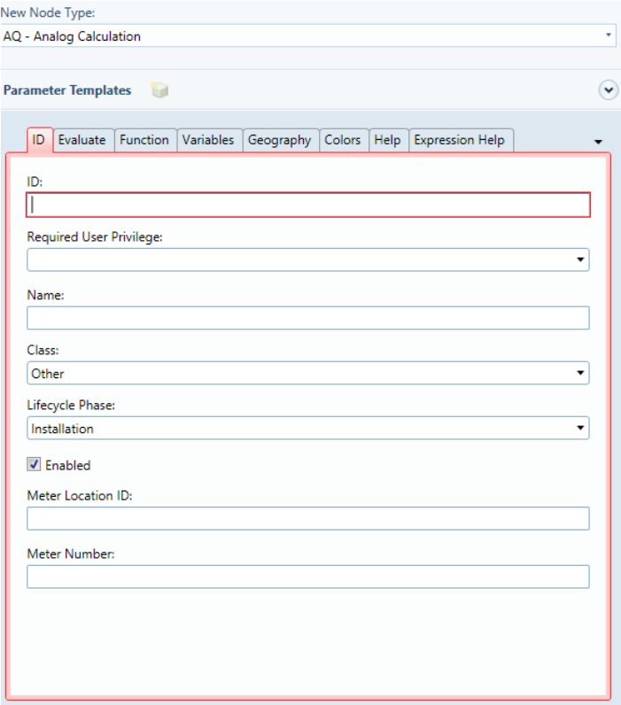
The below table describes the fields involved. Suitable name standard might be to number the objects and a description of the purpose. Example AQ01 – Lowest Room Temp.
AT – Average Temperature Object
There is a special object in IMC to calculate average temperature. You can use script functions to perform the same functionality, but the AT Object simplifies this calculation. It is typically used to control heating for a building by using average room temperature instead of heating flow.
Create an AT Object by adding this to objects in topology.
Next step is to select the room sensors and set the parameters on the Function Tab
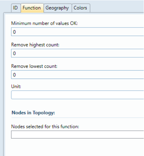
-
Minimum Number of Values OK
To avoid controlling when many sensors are lost, it is possible to set minimum number of sensors. If less sensors then minimum, the average will be “sensor error”
-
Remove Highest Count
If a number > 0 is entered, the algorithm will exclude the x highest temperatures from average calculation, where x is the number entered,
-
Remove Lowest Count
If a number > 0 is entered, the algorithm will exclude the x highest temperatures from average calculation, where x is the number entered,
-
Unit
Normally select °C here.
-
Nodes in Topology
Select the temperature sensors to include in calculation here,
AV Analog Value Object
Used to create analog alarm from third party devices (eg Modbus).
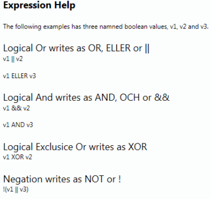
DQ – Digital Expression Object
Similar to the AQ object but used for digital signals. Expressions are made using AND/OR commands.
DV Digital Value Object
Used to create digital alarm from third party devices (eg Modbus).
HO Holidays Object

LR Linear Regulator Object
Used to do a linear curve with two breakpoints.
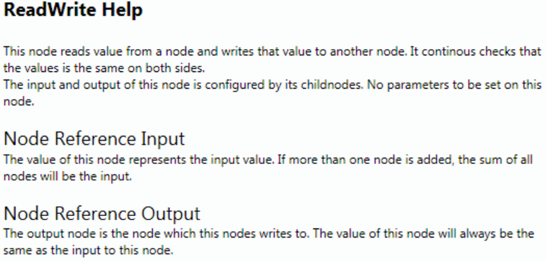
RW ReadWrite ObjectKonfigurationsmanual, KTC-IMC
ST State Object
ST State Sequence Object
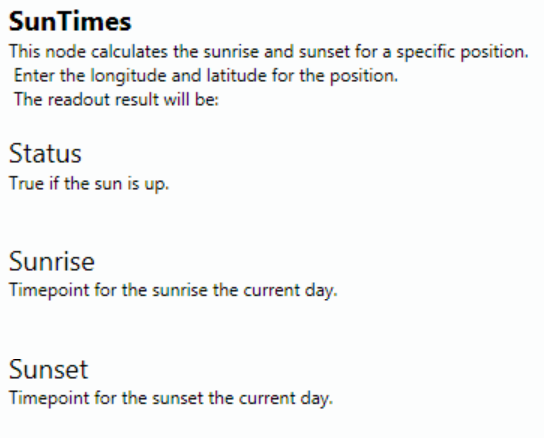
SU SunTimes Object
TM Thermostat Object
Used to do thermostats function with on and off- time delay.
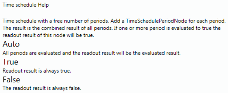
TU Timeschedule Object
Creating IMC Alarms and Trend Data
How to set up polled Alarm using AV/DV Objects
To create polled alarms, we use the AV / DV objects (for SRDLink alarm see further down in this manual). First a physical Object (eg Modbus objects) needs to be linked to an AD / DV Object. After this you have to set the alarm options via the “Alarm” tab described below. Via the "Evaluate" tab it’s possible to set the time for the polling interval (default is 60sec).
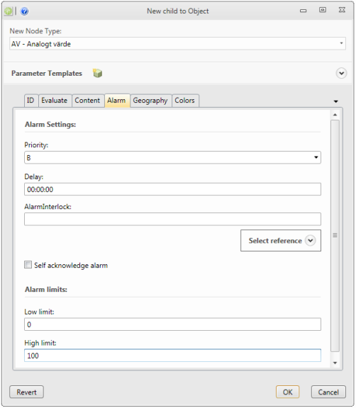
-
Priority required
Off, A,B or C
-
Delay required
Time delay for the alarm.
-
AlarmInterlock optional
Ability to connect an object to use for interlock of the alarm.
-
Self acknowledge alarm optional
(AutoAcknowledge) If the alarm should be autoacknowledged or not.
-
Low limit required
Low alarm limit setpoint.
-
High limit required
High alarm limit setpoint.
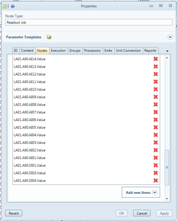
How to set up polled Trend Data
IMC is able to poll trend data. This is done using a predefined job named "ReadoutMomentary_10min". By connecting objects to this job, you will enable trend on these signals. Objects are added via the "nodes" tab in the "ReadoutMomentary_10min" job. Alternatively, you can drag objects from the "Topology" to the job.
How to set up Alarms for SRDLink devices
Alarms from SRDLink devices are activated in the "SRDLink Gateway" and the "DUC (SRD Link)" by checking the "Scan alarms" box. The IMC will then poll the activated alarms in KTC SRD Link devices.
Note: You can also configure the SRDLink devices to send alarms to the IMC. This requires that a receiver is set up in SRDLinkServer. Typically, this receiver address will be set to "0". This is not necessary but will speed up the alarm handling as it will be handled as an event.
How to set up Trend Data for SRDLink devices
SRD devices have built-in-trend buffer. At IMC, we can determine which object we want to retrieve history from and save in the IMC database. There are several ways to activate history on the objects.
- Using SRDLink View
- On each object
- Several at once using the details Topology
Activate Trend Data collection via SRDLink View
Mark the Topology tab and select View / SRDLink View.
Select the SRD device you want to activate Trend Collection on. In SRDLink View window, you will now get the option to enable collection of history on each individual object. This is done by expanding the object and then tick the Value box.
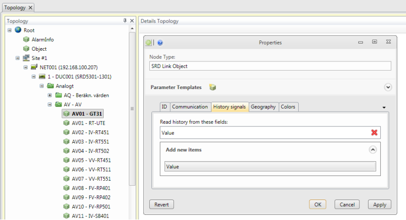
Activate Trend Data collection manually on every object
Select the object you want to activate Trend Collection on through the Topology tree and select Edit (F4). Select the tab "History signals" and the Add New Items "Value".
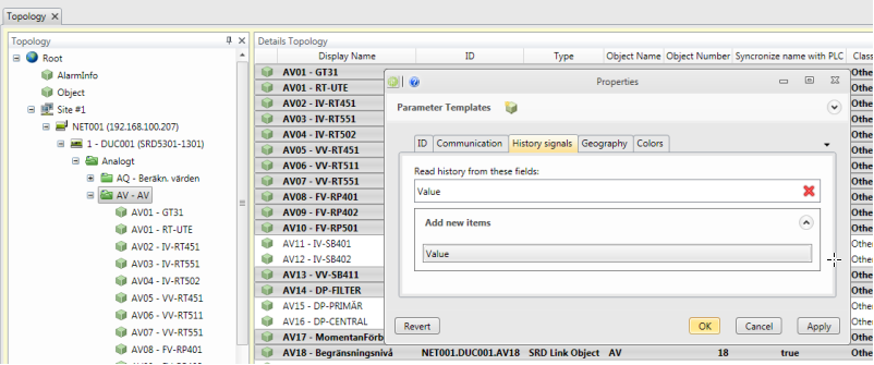
Activate Trend Data collection on several objects at the same time
Select the object you want to activate Trend Collection on in the Details Topology. Select Edit (F4). Select the tab "History signals" and the Add New Items "Value". All selected object will now be activated.
General settings for the retrieval of historical values.
Start by opening Data Source/Metering/Jobs.
Mark ReadHistory and select Edit.
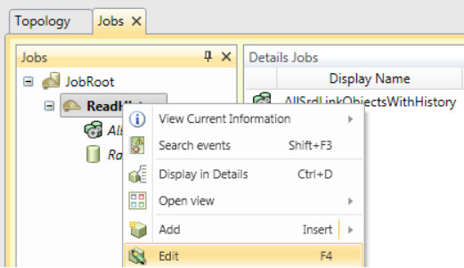
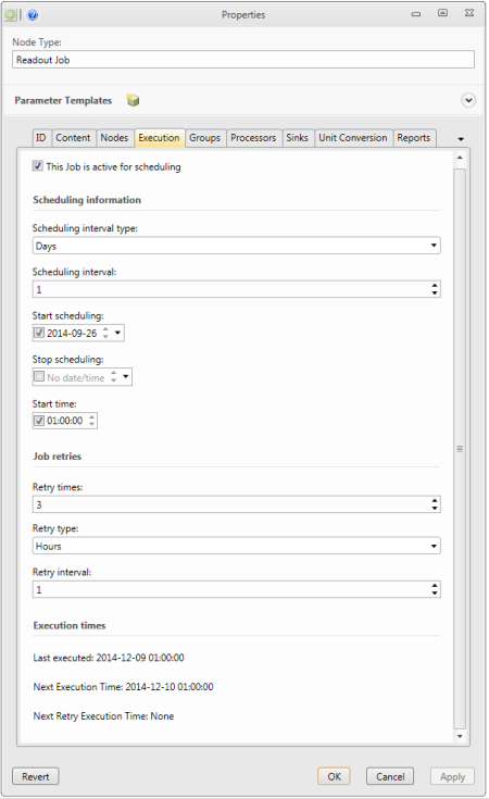
Choose Execution to change the setup for scheduling of the job.
-
This job is active for scheduling required
If not selected the scheduler will never schedule this job for execution.
-
Scheduling interval type required
Specify interval type used by the scheduler to determine next execution time.
-
Scheduling interval required
Specify the interval used by the scheduler to determine next execution time. For instance ‘2’ results in scheduling every other of the type specified(hour, day, etc)
-
Start scheduling required
Enter the day for when the scheduler starts scheduling the job. If empty, today is used as starting point for scheduling.
-
Stop scheduling required
Enter the day for when the scheduler ends scheduling the job. If empty, the scheduler keeps schedule new execution times forever.
-
Start time optional
Enter the time of day for the execution to begin(scheduling is performed during the start-end time interval, using execution to decide how often). If not specified the start of the day is used.
-
Retry times optional
Specify the number of retries the job does for erroneous results. Only erroneous results are retried. If specified to 0 no retries will be performed by the job.
-
Retry type optional
Specify interval type used by the job to determine next retry time.
-
Retry interval optional
Specify the interval used by the job to determine next retry time. For instance ‘2’ results in retries every other of the type specified(hour, day, etc)
Creating IMC Web GUI
Creating a slide Show
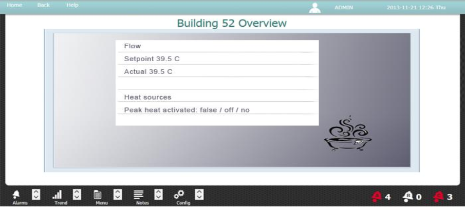
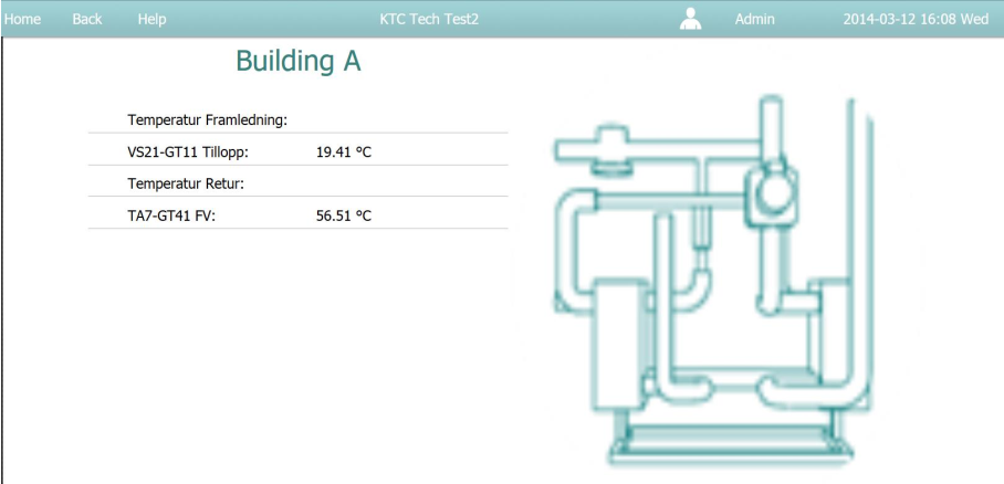
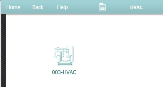
The building manager accesses the system via a web interface. This interface can be customized to present a view of the functions the manager finds most pertinent to his/her specific application. Included in customization is an opening Slide that presents the functions, readouts, menus etc. that a building manager wants to see immediately upon opening the page.
The following is an example of the web interface that is used by a building manager to monitor the system.
In this view, you can see an example of the opening page with a customized slide show that presents the selectable items specific to the managers primary daily concerns for that building. Note that you can create any number of pages and browse through them upon opening the interface:
How a slideshow is composed
Open the IMC/Slide datasource:
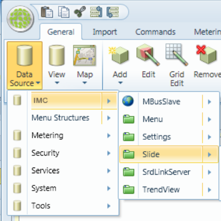
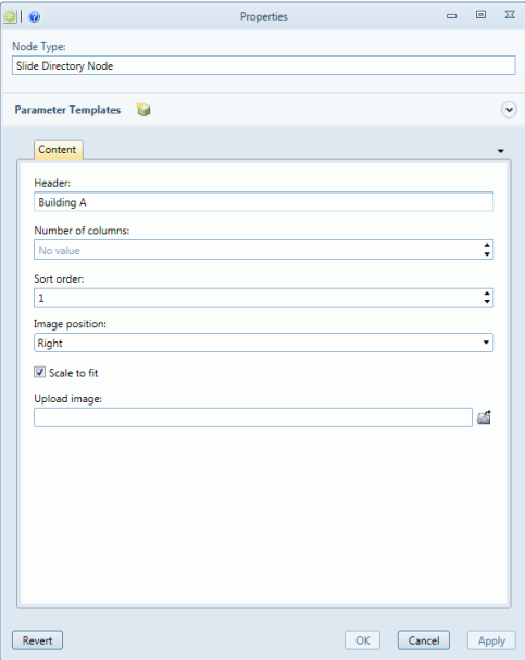
Right-click the root node selecting the Add / Slide Directory Node option:
-
Header required
Header of the slide.
-
Number of columns required
Number of columns, one or two. Two columns only available when image position is center.
-
Sort order required
Which order the header will be displayed.
-
Image position required
Left, right or center
-
Scale to fit Optional
Scale image to fit on slide.
-
Upload image Optional
Upload an image to show as background in the slide
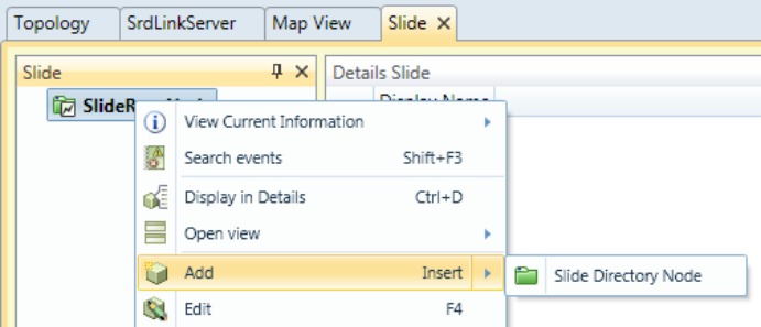
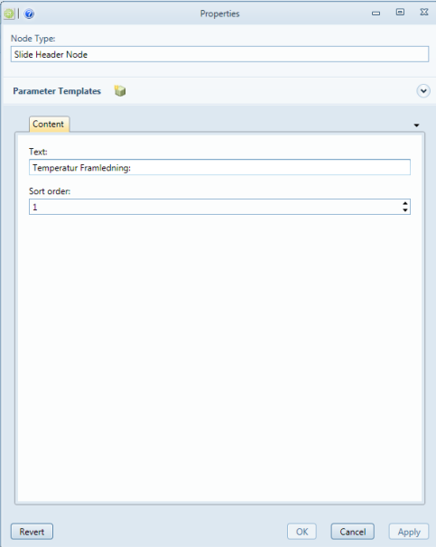
After this you have to add SlideHeaderNode and SlideNodeReference.
SlideHeaderNode is a superscription and SlideNodeReference is a link to your dynamic object in the topology.
-
Text required
Text to display.
-
Sort order required
Which order the text will be displayed.
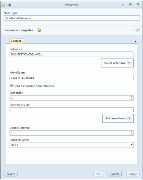
-
Reference required
Enter a node ID specifying the reference to a node
-
Menu Name Optional
This name will be shown in the menu.
-
Read menu name from reference Optional
Read the menu name from the node reference.
-
Sort order required
Which order the values will be shown.
-
Show this fields Optional
Default field is Value. Here you can change it to another.
-
Update interval required
Update interval in seconds for this node.
-
Userlevel write required
Minimum userlevel for configure node.
A typical slideshow image may look as below.
Creating a menu
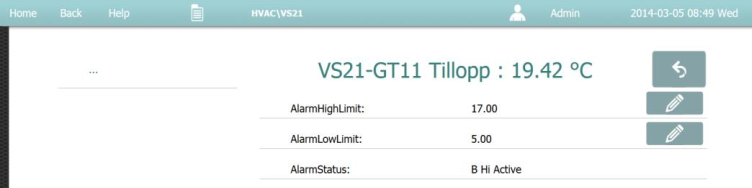
In addition to slideshows, you can create system-specific menus tailored to the end user needs. In the user menu, you can change setpoints, alarm priority, etc.
How a menu is composed
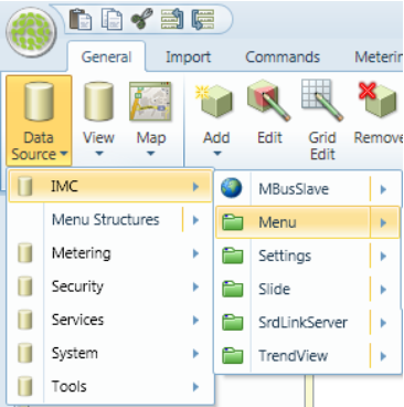
Open DataSource/IMC/Menu:
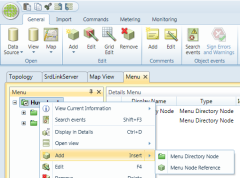
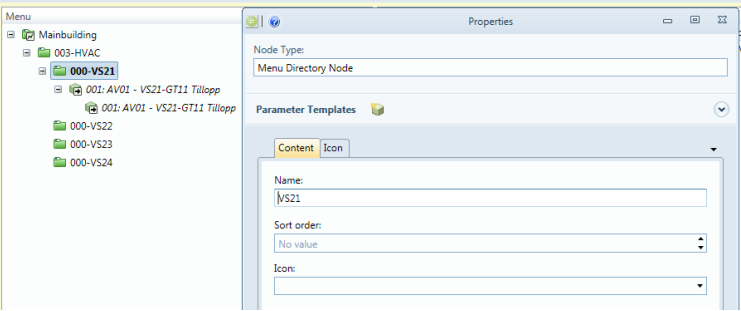
Start by adding a Menu Directory Node:
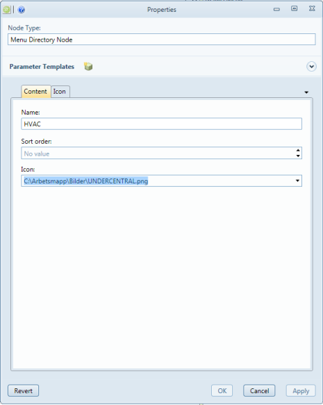
-
Name required
Name of the node. It appears in the tree.
-
Sort order optional
Used to sort the nodes in the tree.
-
Icon optional
Ability to connect a picture/icon to the Name.
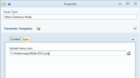
-
Icon optional
Select picture/icon to upload.
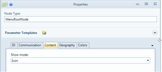
Note: to activate the icons. Choose MenuRootNode / Content and select Show mode: Icon
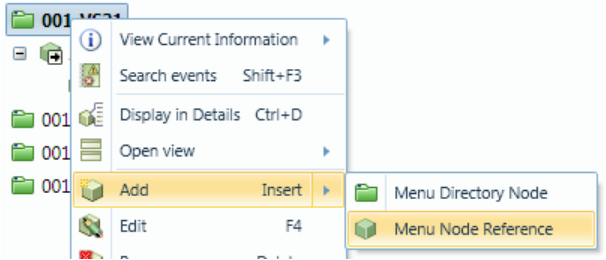
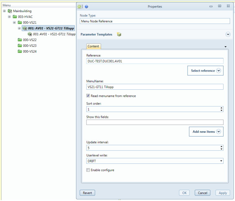
When you are satisfied with the structure (Menu Directory Node) it’s time to continue with Menu Node Reference. Use the Menu Node Reference to link the objects that you have in the Topology tree together with your user menu.
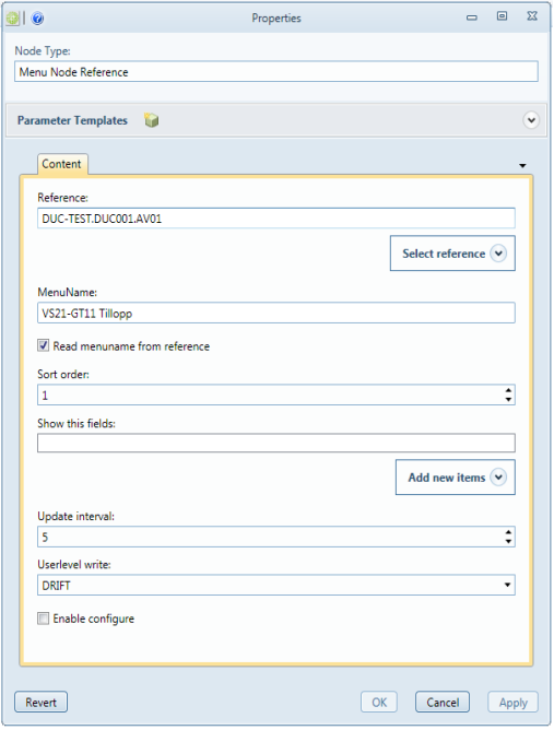
-
Reference required
Select the reference to the object you want to show in the menu.
-
MenuName required
The name shown in the menu. Read menu name from reference optional Read the menu name from the node reference.
-
Sort order optional
Used to sort the nodes in the tree. Show this fields optional Ability to customize which fields to display. Default is Value.
-
Update interval required
Update interval in seconds.
-
Userlevel write required
Minimum userlevel for configure node.
-
Enable configuration optional
Enable configure node or not.
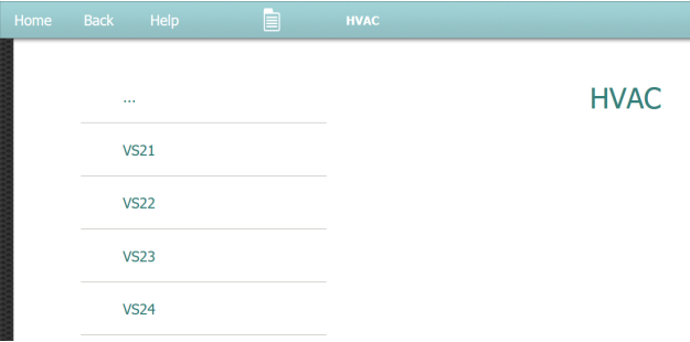
Example: Configuration as below provides the following web interface.
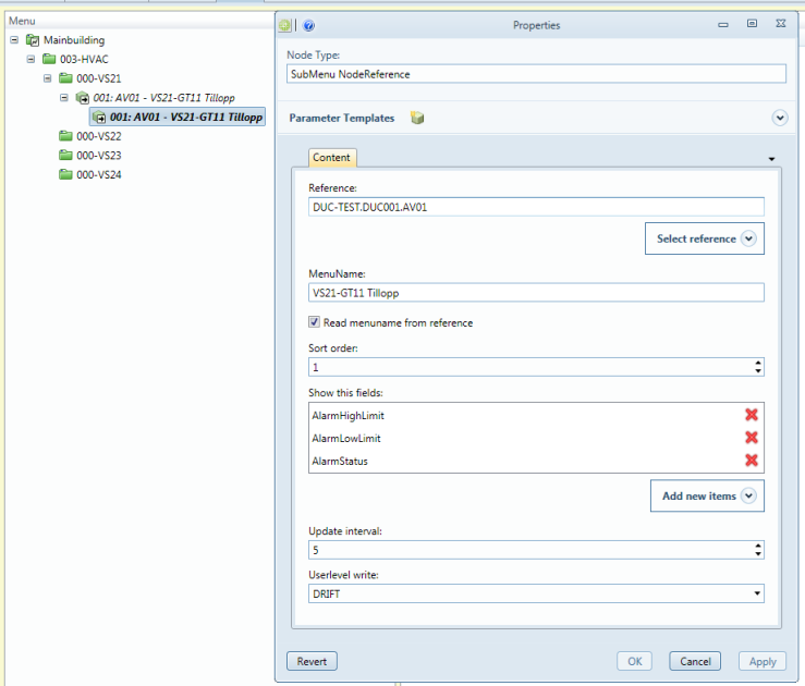
Web Interface:

Creating a TrendView
How a TrendView is composed
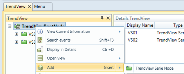
Open the IMC/Trendview datasource.
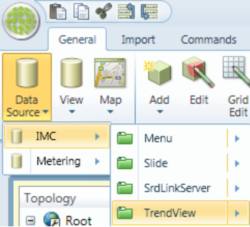
Right-click the root node selecting the TrendView Serie Node.
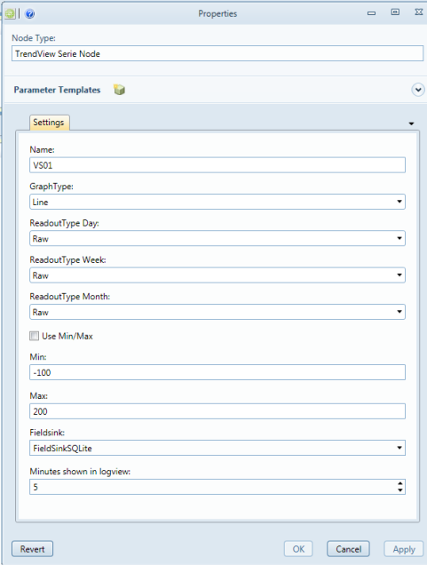
-
Name required
Name on the TrendView
-
GraphType required
Line/Curve
-
ReadoutType Day required
Select type of values to read from fieldsink in day mode. Raw/Hour/Day/Month
-
ReadoutType Week required
Select type of values to read from fieldsink in week mode. Raw/Hour/Day/Month
-
ReadoutType Month required
Select type of values to read from fieldsink in month mode. Raw/Hour/Day/Month
-
Use Min/Max optional
If checked, the Min/Max settings will be used.
-
Min optional
Min value in graph.
-
Max optional
Max value in graph.
-
Fieldsink required
Select fieldsink to read data from.
-
Minutes Shown in logview required
Minutes shown in logview.
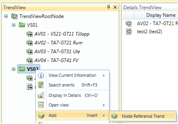
After this you have to connect your node reference(max 4 per TrendView).
Right-click on the TrendView Serie Node and select Node Reference Trend.
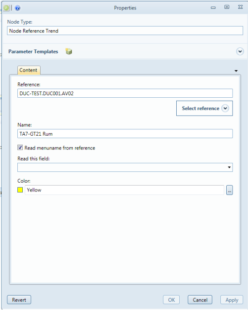
-
Reference required
Enter a node ID specifying the reference to a node.
-
Name required
Name shown in graph
-
Read menuname from reference optional
Read the menuname from the node reference.
-
Read this field optional
Select the field you want to read. Default is Value.
-
Color required
Select color.
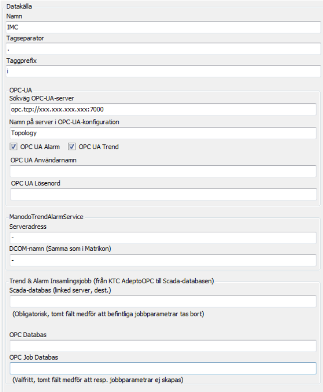
Connecting to KTC Scada
The IMC has built-in support for OPC UA, which we use when we want to communicate with KTCSCADA. We use the tool KTC Manager to add a new data source to establish communication with IMC OPC UA. Things to consider is that the OPC UA communicates on port 7000 and that in this case we are using OPC UA Alarms and Trend.
Creating IMC dynamic flowchart/diagram
Starting with version 1.2 the IMC has support for creating dynamic diagrams. Construction of the diagrams is done using an additional module to the CMT tool called Diagram Designer.
In short, construction of diagrams is done by adding dynamic symbols and value boxes onto an imported background. The background image may be in the format BMP, JPEG, PNG, or TIFF.
More simple drawing functions such as Ellipse, Line, Polygon, Polyline, and Rectangle are available in version 1.2
Dynamic color changes, for example on sensors and fan symbols are made in version 1.2 by using conditions to switch between different static images.
It is also possible to save dynamic object to the Designer library. Some standard symbols are supplied at installation but the idea is that the user expands this library for their own specific needs.
How to create a new diagram
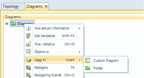
The Diagrams tab
Diagrams are used to add new or edit existing diagrams. There is also an opportunity to preview the results of the work done in the "Diagram Designer".
Diagrams tab is opened via the “Data Source / Diagrams / Diagrams”.
New diagrams and folders are added as follows:
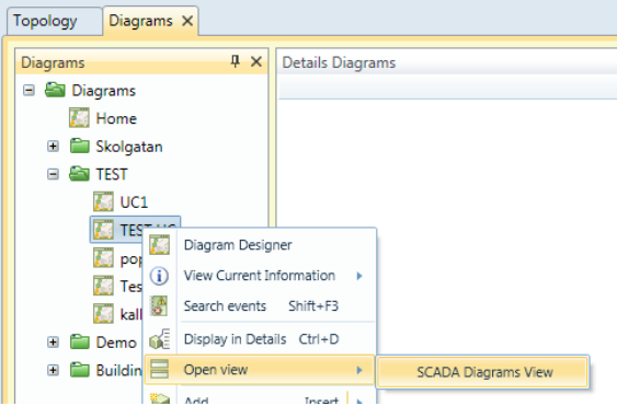
How to preview or view a previously produced diagram via Diagrams View is shown below:
Start Diagram Designer
Open Diagram Designer by right-clicking on the "Custom Diagram" you want to edit and select Diagram Designer.
Adding a background image
In Diagram Designer, right-click on the diagram and choose from the selections below:
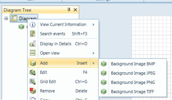
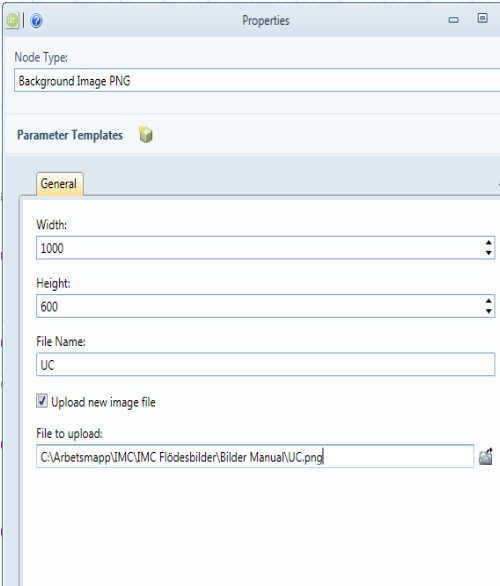
-
Width
Width of the imported image in pixels.
-
Height
Height of the imported image in pixels.
-
File Name
File name of the image.
-
Upload new image file
If checked, you can upload a new image file to the location specified above.
-
File to upload
File to upload and save to the location specified above.
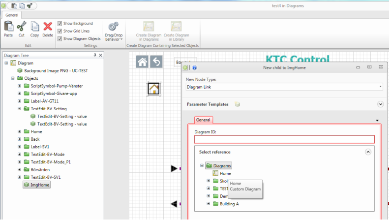
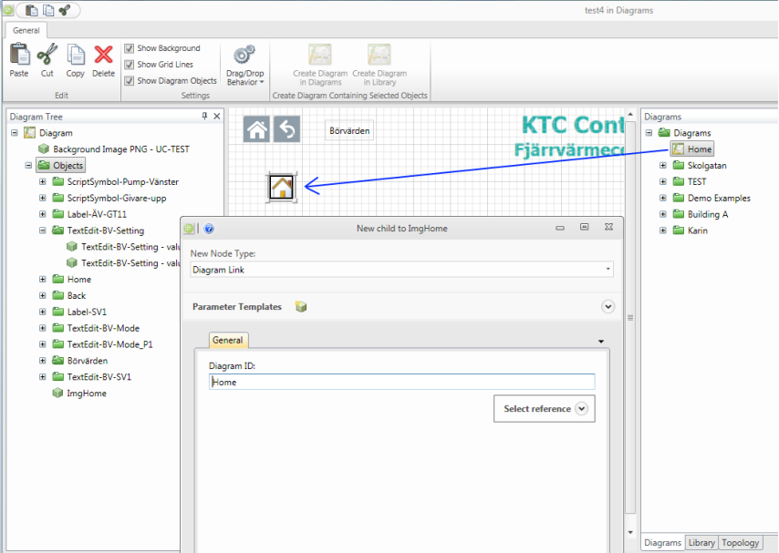
Create a diagram link
Start by dragging a link symbol from "Libary" or create a new symbol that you want to use as a link.
Alt.1
Right click on your symbol and select Add / Diagram Link.
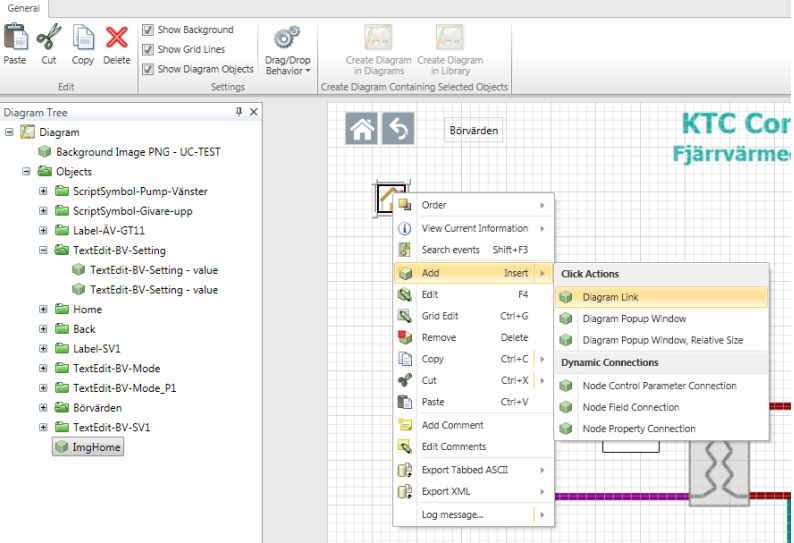
Select the diagram you want to create a link to.
Alt.2
Make sure the drag / drop behavior is set to "Create Diagram Link".
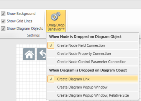
Hold down the "Alt" key and drag the diagram to the symbol you want to create a link to.
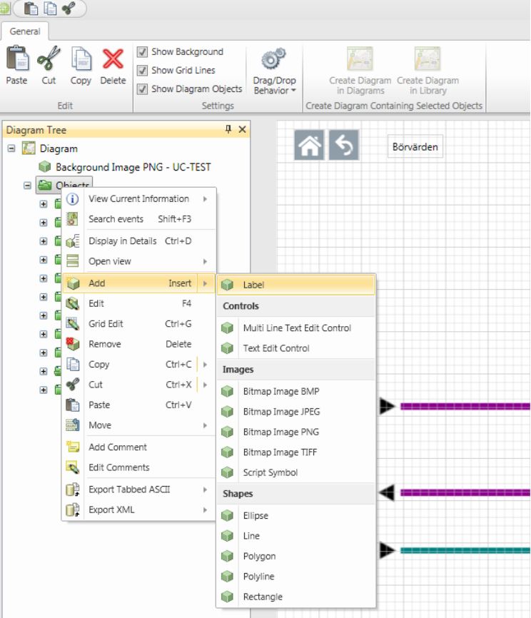
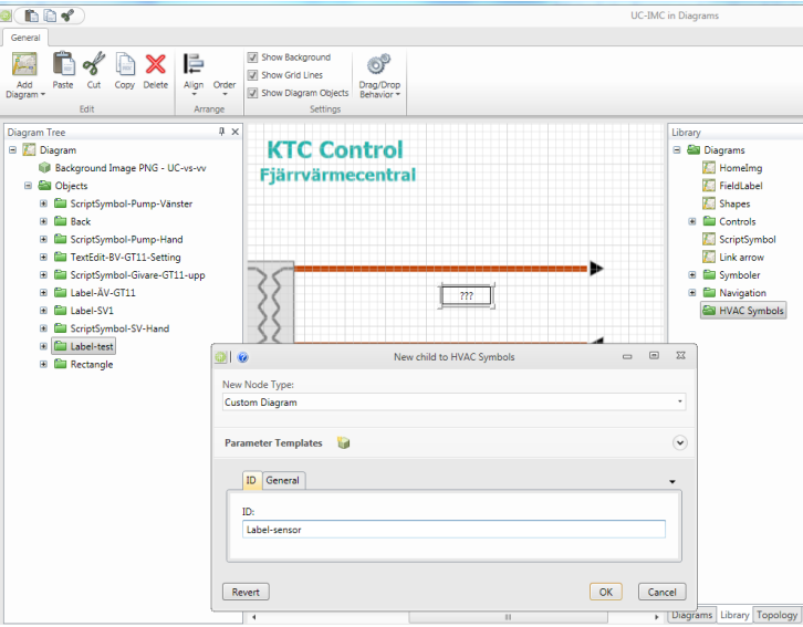
Creating a value box
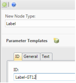
Start by adding a new Label.
Fill in an ID name under the "ID" and a text string under "text".
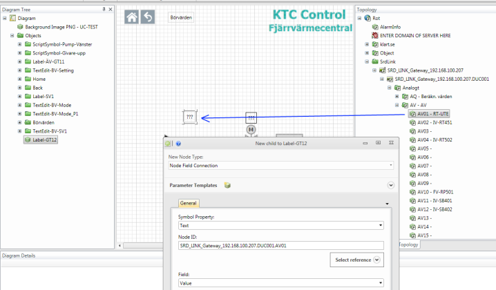
To attach a Node to the Label can then be done in two ways.
Alt.1
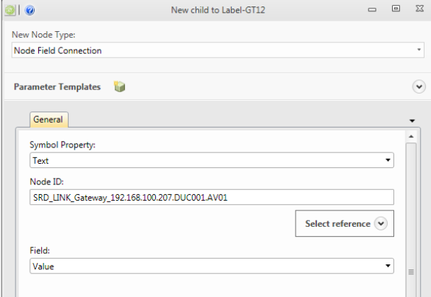
Right-click on your new "Label" and select "Node Field Connection."
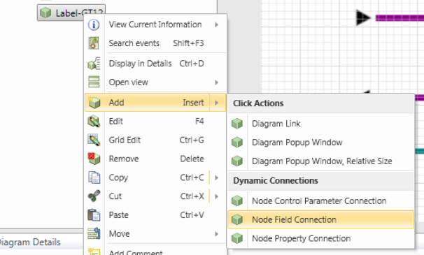
Symbol Property will in this case be Text. Select the node you want to be displayed, and finally which field on the selected node to be displayed.
Alt.2
Make sure the drag / drop behavior is set to “Create Node Field Connection”.
Select the node that you want to connect with the "Label" by dragging the Node from the Topology tree. Symbol Property will in this case be Text and finally select the field to be displayed.
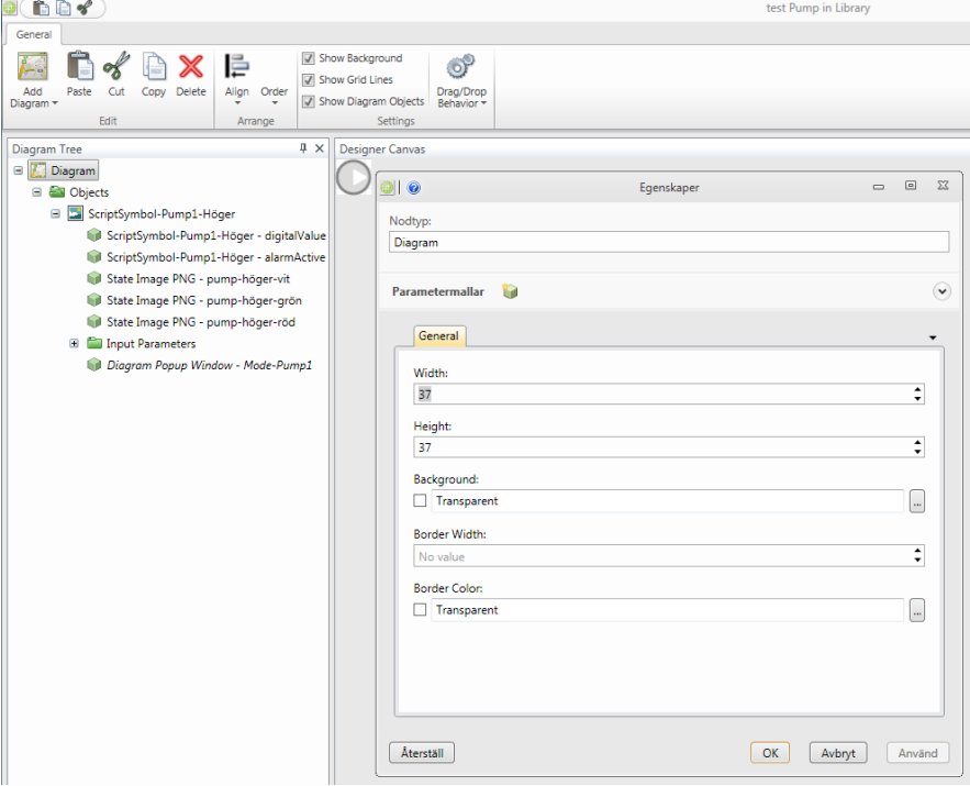
Creating a new dynamic symbol
Dynamic color changes, for example on sensors and fan symbols are made in version 1.2 by using conditions to switch between different static images.
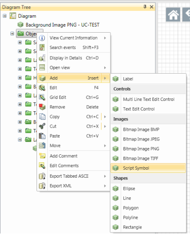
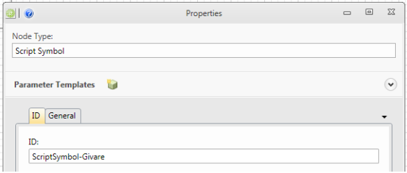
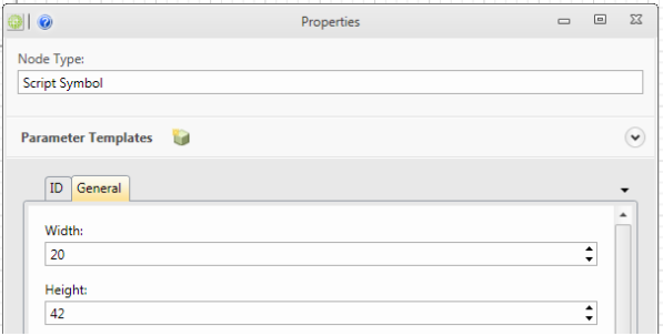
Add a "Script symbol"
Enter an ID that will harmonize with the symbol to be created.
Also enter the width and height of your symbol in the General tab.
Add the static images to be used in the symbol. Mark your new Script Symbol and select/add State images.


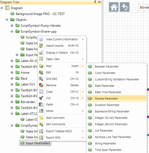
After this, we want to determine the condition that is the basis for the shifting of the static images. The first thing we must do is to add the Script parameters / input parameters. In this example, we want a sensor symbol to change from "white" to "red" when the alarm is active. In this case we need to create a “Double Parameter”.
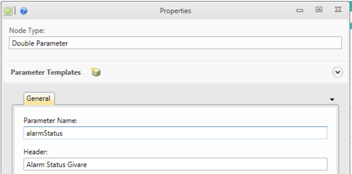
Fill in an appropriate name of "Parameter Name" and "Header".
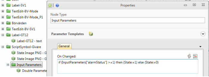
Go back to the "Input Parameters" and create your script:
What now remains is the "physical" connection to the node. This connection is created by adding a "node field connection”. Symbol Property is chosen to the one we created in the "Input Parameters", in this case "Alarm Status Sensor".
Creating an editable value box
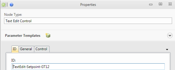
Add a "Text Edit Control"
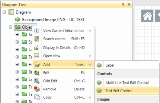
Enter an ID that will harmonize with the object to be created.
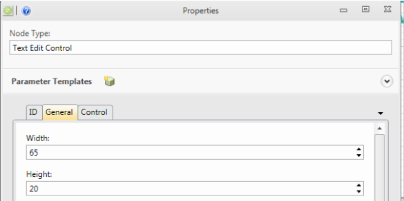
Enter the width and hight of the text box under the General tab.
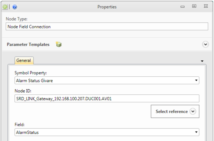
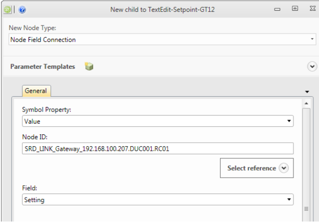
Add a "Node Field Connection"
Select “Value” in Symbol Property and edit the Node ID and Field.
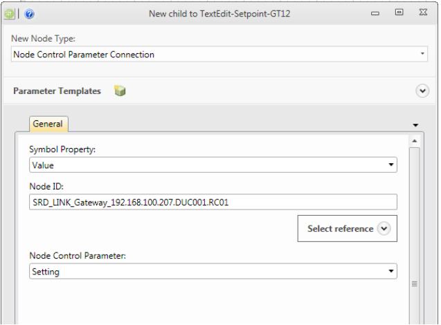
In order to write down to the node, we also need a "Node Control Parameter Connection" as shown below.
Create a description that is linked to the Diagram
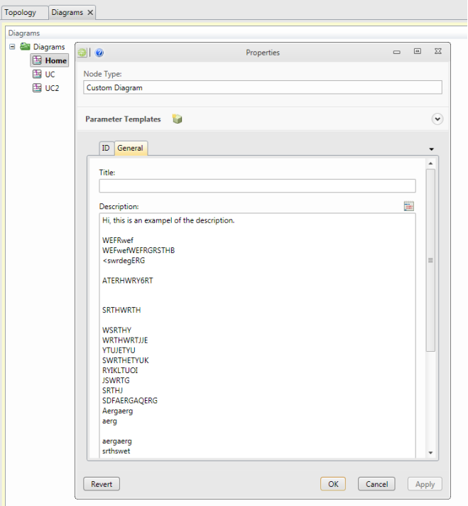
When the users open a diagram via the web interface (or via the app.) he will have a description
symbol up in the left corner by default  .
.
When the user clicks on this icon he will get up a customized text that usually describes the function of the specific diagram.
How to create or edit this text is shown below.
- In CMT/ Diagrams, mark the current diagram and select edit.
- Select the General tab and then type or paste your text in the description.
How to save Objects to library
- Select the object in the diagram canvas that you want to save as a symbol.
- Open the Library tab and select the folder where you want the symbol to be saved.
-
Click "Add Diagram" and select "Add Diagram Containing Selected Objects in Diagram Canvas".
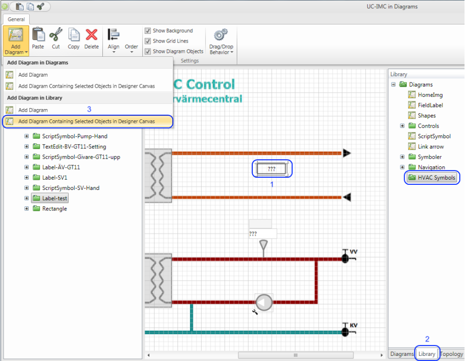
-
Choose an appropriate name for the symbol and click OK to save.
-
Open the newly created symbol/diagram in Diagram Designer and adjust the width and height so it harmonizes with the symbol. (This is to more easily place the symbol in the right place when you create diagrams with symbols.)
How to Copy/Paste and XML Export/Import of Custom Diagrams and Folders in the Diagrams/Library data sources
Copy/Paste objects in the Diagrams/Library data source from Server 1 to Server 2
-
Start a CMT and login to Server 1
-
Open the Diagrams/Library data source
-
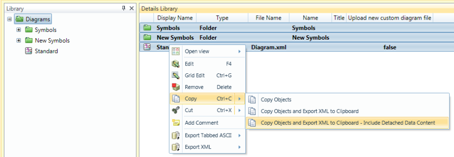
Select the objects that you want to copy, such as some Custom Diagrams or Diagram Folders. In the example below, a number of child objects under the root object are selected.
-
Right click and select Copy with the option Copy Objects and Export XML to Clipboard – Include Detached Data Content
-
-
Start a second CMT connected to Server 2
-
Open the Diagrams/Library data source
-
In the data source, select the Parent object to which the objects will be pasted. In the example here, the root object is selected as the parent.
-
Right click and select Paste.
- Note: Paste corresponds to an Import XML scenario with the import option Create New Objects.
-
The new objects and all the file content are pasted at Server 2.
-
Export/Import objects in the Diagrams/Library data source from Server 1 to Server 2
-
Start a CMT and login to Server 1
-
Open the Diagrams/Library data source
-
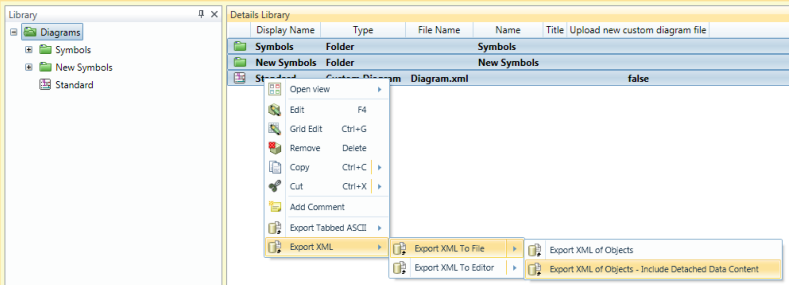
Select the objects that you want to copy, such as some Custom Diagrams or Diagram Folders
-
Right click and select Export XML To File with the option Export XML of Objects – Include Detached Data Content.
- Note: When Detached Data Content is included in the export, it is recommended to use Export XML To File (NOT Export XML To Editor), as the detached data can be very large. This will export the content directly to a file instead of open the XML for the exported data and the file content in the editor.
-
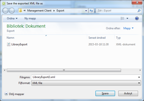
Save the exported data to a XML file.
-
-
Start a second CMT connected to Server 2
-
Open the Diagrams/Library data source
-
In the data source, select the Parent object to which the objects should be imported, e.g. the root object.
-
Right click and select Import XML From File with the import option Create New Objects.
-
Select the file exported from Server 1, and click Open.
-
The new objects and all file content are imported to Server 2.
-